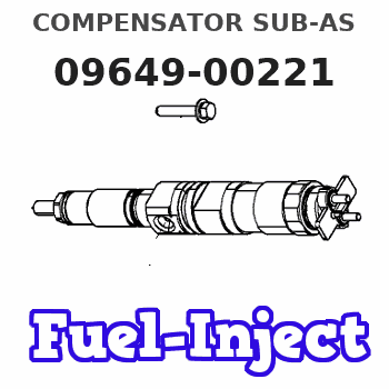
Information compensator sub-as
Rating:
Scheme ###:

| 000. | [01] | 09649-00221 | COMPENSATOR SUB-AS | |
| 000. | [01] | 09649-00221 | COMPENSATOR SUB-AS | |
| 001. | [01] | 09644-00351 | COVER SUB-ASSY, GO | 22703-87704-000 |
| 001. | [01] | 09644-00351 | COVER SUB-ASSY, GO | |
| 002. | [01] | 09644-00320 | COVER SUB-ASSY, GO | 22703-64520-000 |
| 002. | [01] | 09644-00320 | COVER SUB-ASSY, GO | 22703-64520 |
| 003. | [01] | 09621-60030 | STOPPER, TIMER SLI | 22419-87701-000 |
| 003. | [01] | 09621-60030 | STOPPER, TIMER SLI | 22658-64518 |
| 004. | [01] | 09646-50391 | R0D, PUSH | 22321-64850-000 |
| 004. | [01] | 09646-50391 | R0D, PUSH | 22321-64850 |
| 005. | [01] | 09611-80160 | BUSHING, GUIDE | 22348-87702-000 |
| 005. | [01] | 09611-80160 | BUSHING, GUIDE | 22348-64360 |
| 006. | [01] | 19263-10010 | DIAPHRAGM | 22303-87701-000 |
| 006. | [01] | 19263-10010 | DIAPHRAGM | 22542-54260 |
| 007. | [01] | 09624-60020 | SHEET, PLUNGER SPR | 22143-54260 |
| 007. | [01] | 09624-60020 | SHEET, PLUNGER SPR | 22143-87702-000 |
| 008. | [01] | 09611-80190 | BUSHING, GUIDE | 22348-87701-000 |
| 008. | [01] | 09611-80190 | BUSHING, GUIDE | 22348-54490 |
| 009. | [01] | 94905-04070 | NUT, HEXAGON | 90099-05156 |
| 009. | [01] | 94905-04070 | NUT, HEXAGON | 22493-87702-000 |
| 010. | [01] | 09621-10070 | CLIP, TIMER | 22656-54490 |
| 010. | [01] | 09621-10070 | CLIP, TIMER | 22293-87701-000 |
| 011. | [01] | 09645-50090 | PIN, LEVER CONECTI | 22338-87701-000 |
| 011. | [01] | 09645-50090 | PIN, LEVER CONECTI | 22338-54120 |
| 012. | [01] | 09611-80020 | BUSHING, GUIDE | 22348-54121 |
| 012. | [01] | 09611-80020 | BUSHING, GUIDE | 22348-87703-000 |
| 013. | [01] | 09625-40021 | NUT, GOVERNOR SHAF | 22722-87702-000 |
| 013. | [01] | 09625-40021 | NUT, GOVERNOR SHAF | 22722-54120 |
| 014. | [01] | 94901-81680 | WASHER, COPPER PLA | 90099-01473 |
| 014. | [01] | 94901-81680 | WASHER, COPPER PLA | 22119-87702-000 |
| 015. | [01] | 09604-90230 | O-RING | 22193-55031 |
| 015. | [01] | 09604-90230 | O-RING | 22193-55031-000 |
| 016. | [01] | 09627-20040 | PIN, LEVER SUPPORT | 22526-87701-000 |
| 016. | [01] | 09627-20040 | PIN, LEVER SUPPORT | 22526-54120 |
| 017. | [01] | 09629-50070 | LEVER SUB-ASSY, CO | 22308-87702-000 |
| 017. | [01] | 09629-50070 | LEVER SUB-ASSY, CO | 22308-54120 |
| 017. | [01] | 09629-50670 | LEVER SUB-ASSY, CO | |
| 017. | [01] | 09629-50670 | LEVER SUB-ASSY, CO | |
| 018. | [02] | 09024-80010 | WASHER, DRAIN SCRE | 22378-76010 |
| 018. | [02] | 09642-60110 | GASKET, DELIVERY V | 22149-6D450-000 |
| 018. | [02] | 09024-80010 | WASHER, DRAIN SCRE | 22378-87701-000 |
| 018. | [02] | 09642-60110 | GASKET, DELIVERY V | 22149-6D450 |
| 019. | [04] | 09644-90130 | BOLT, SOCKET | 22395-54263 |
| 019. | [04] | 09644-90130 | BOLT, SOCKET | 22395-54263-000 |
| 020. | [02] | 09626-90032 | BOLT, GOVERNOR LIN | 22739-54120 |
| 020. | [02] | 09626-90032 | BOLT, GOVERNOR LIN | 22739-87703-000 |
| 021. | [01] | 09604-90180 | O-RING | 22193-54561 |
| 021. | [01] | 09604-90180 | O-RING | 22292-87703-000 |
| 022. | [01] | 94905-05430 | NUT, HEXAGON | 90099-05252 |
| 022. | [01] | 94905-04100 | NUT, HEXAGON | 90099-05181 |
| 022. | [01] | 94905-05430 | NUT, HEXAGON | 90092-05252-000 |
| 022. | [01] | 94905-04100 | NUT, HEXAGON | 22493-87703-000 |
| 023. | [01] | 90200-08211 | WASHER, PLATE | 90093-00802 |
| 023. | [01] | 90200-08211 | WASHER, PLATE | 22113-87701-000 |
| 024. | [01] | 90176-06361 | NUT, HEXAGON | 90092-20608 |
| 024. | [01] | 90176-06361 | NUT, HEXAGON | 22135-87701-000 |
| 025. | [01] | 09602-00110 | SCREW SUB-ASSY, OV | 22160-87702-000 |
| 025. | [01] | 09602-00110 | SCREW SUB-ASSY, OV | 22160-54262 |
| 026. | [01] | 09642-60120 | GASKET, DELIVERY V | 22149-54800-000 |
| 026. | [01] | 09024-10010 | WASHER, AIR BLEEDE | 22119-77020-000 |
| 026. | [01] | 09642-60120 | GASKET, DELIVERY V | 22149-54800 |
| 026. | [01] | 09024-10010 | WASHER, AIR BLEEDE | 22119-77020 |
| 027. | [01] | 09031-70130 | PLUG, SCREW | 22129-54120-000 |
| 027. | [01] | 09031-70130 | PLUG, SCREW | 22129-54120 |
| 028. | [1C] | 09649-20150 | SPRING, BOOST COMP | 22546-54490 |
| 028. | [1C] | 09649-20170 | SPRING, BOOST COMP | 22546-54492-000 |
| 028. | [1C] | 09649-20170 | SPRING, BOOST COMP | 22546-54492 |
| 028. | [1C] | 09649-20160 | SPRING, BOOST COMP | 22546-54491-000 |
| 028. | [1C] | 09649-20150 | SPRING, BOOST COMP | 22546-54490-000 |
| 028. | [1C] | 09649-20160 | SPRING, BOOST COMP | 22546-54491 |
| 030. | [01] | 19263-30010 | WASHER, THRUST | 22332-87701-000 |
| 030. | [01] | 19263-30010 | WASHER, THRUST | 22549-17140 |
Include in #3:
09649-00221
as COMPENSATOR SUB-AS
09649-00221
Cross reference number
| Part num | Firm num | Firm | Name |
| 09649-00221 | COMPENSATOR SUB-AS |
Information:
Introduction
Do not perform any procedure in this Special Instruction until you read this information and you understand this information. This Special Instruction is intended for the installation of the 257-4183 Injector Wiring Harness Kit . The 257-4183 Injector Wiring Harness Kit can be used to repair fuel injector connectors.
Table 1
Required Tools
Tool Part Number Part Name Qty
A 9S-9150 Terminal Crimp Tool As 1
B 9U-6070 Heat Gun Gp 1 Removal of a Faulty Connector from the Wire Harness
The following steps can be used in order to remove a faulty connector for an injector on the wire harness that is located under the valve mechanism cover.
Identify the connector that needs to be replaced. Wiring for the injector solenoid is not sensitive to polarity.
Illustration 1 g01111254
Connector that is cut from the wire harness
Cut wire (1) at a distance of 70 mm (2.8 inch) from the rear surface of the connector.
Cut wire (2) at a distance of 65 mm (2.6 inch) from the rear surface of the connector.
Illustration 2 g01111314
(3) Wire from the harness for side (B) on the connector (4) Wire from the harness for side (A) on the connectorNote: The wires on the old connector are cut to length so that the wires on the wire harness will match up to the new connector. Cutting the wires to the proper length will aid in matching the harness wires to the wires on the new connector.
Discard the old connector.Installation of a New Connector
The following steps can be used in order to install a new connector for an injector on the wire harness that is located under the valve mechanism cover.
Use Tool (A) in order to remove 5 mm (0.2 inch) of the plastic from wires (3) and (4) .
Illustration 3 g01111333
Connecting the connector to the wire harness (A) Side (A) of the new connector (B) Side (B) of the new connector (3) Wire from the harness for side (B) on the new connector (4) Wire from the harness for side (A) on the new connector (5) Heat shrink tubes (6) Butt splice on the wire that is on side (A) of the new connector (7) Butt splice on the wire that is on side (B) of the new connector
Use heat shrink tubes (5) from the 257-4183 Injector Wiring Harness Kit . Slide the heat shrink tubes toward the connector in order to expose the butt splices.
Insert wire (4) into butt splice (6) .
Insert wire (3) into butt splice (7) .