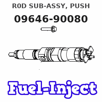
Information r0d sub-assy, push
Rating:
Include in #3:
Cross reference number
| Part num | Firm num | Firm | Name |
| 09646-90080 | 22301-5480 | R0D SUB-ASSY, PUSH | |
| 22301-54800-000 | DAIHATSU | R0D SUB-ASSY, PUSH | |
| 22301-54800 | TOYOTA | R0D SUB-ASSY, PUSH |
Information:
2. Remove bolts (1) from the alternator bracket.3. Remove the bolts that hold plate (3), and remove the plate.4. Disconnect water line (2) from the air compressor. Turn the water line tee toward the lifting bracket in order to provide clearance to remove the head bolt. 5. Remove bolts (4) and (5) that hold the cylinder head assembly to the cylinder block.6. Fasten a hoist, and remove the cylinder head assembly. The weight is approximately 135 kg (300 lb.).
Do not put the cylinder head assembly down on a flat surface. This can cause damage to the fuel injection valves.
7. Remove the gasket, seals (6) and O-ring seal (7) from the spacer plate. The following steps are for installation of the cylinder head. Be sure a new gasket has been installed between the spacer plate and the cylinder block. See Remove And Install Spacer Plate.8. Thoroughly clean the spacer plate and the bottom surface of the cylinder head assembly. Install a new head gasket, new seals (6) and two O-ring seals (7).9. Fasten a hoist, and put the cylinder head assembly in position on the cylinder block. 10. Put clean engine oil on the threads of the cylinder head bolts. Install the cylinder head bolts and washers. Tighten the bolts in sequence shown.a. Tighten bolts 1 through 20 in number sequence to a torque of 270 25 N m (200 18 lb.ft.). b. Tighten bolts 1 through 20 in number sequence to a torque of 450 20 N m (330 15 lb.ft.).c. Tighten bolts 1 through 20 in number sequence to a torque of 450 20 N m (330 15 lb.ft.) by hand.d. Install the rocker shaft assemblies and push rods. See Install Rocker Shaft Assemblies And Push Rods.e. Tighten bolts 21 through 26 in number sequence to a torque of 270 25 N m (200 18 lb.ft.). f. Tighten bolts 21 through 26 in number sequence to a torque of 450 20 N m (330 15 lb.ft.). g. Tighten bolts 21 through 26 in number sequence to a torque of 450 20 N m (330 15 lb.ft.) by hand.h. Tighten the 3/8" bolts (5) to a torque of 43 7 N m (32 5 lb.ft.). If the studs for the exhaust manifold were removed, install new studs, and tighten them to a torque of 25 4 N m (18 3 lb.ft.)11. Make an adjustment to the valves to have a clearance of 0.38 mm (.015 in.) for intake and 0.76 mm (.030 in.) for exhaust. Tighten the locknuts for the valve adjustment screws to a torque of 28 4 N m (21 3 lb.ft.).12. Install the valve cover bases and the inner fuel lines. see Install Rocker Shaft Assemblies And Push Rods.13. Install the valve covers. See Install Valve Covers.14. Install pate (3).15. Connect water line (2) to the air compressor.16. Install bolts (1) for the alternator bracket.17. Install the