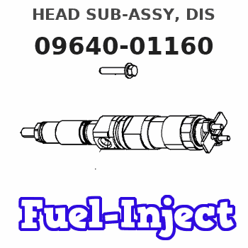
Information head sub-assy, dis
Rating:
Compare Prices: .
As an associate, we earn commssions on qualifying purchases through the links below

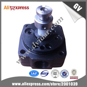
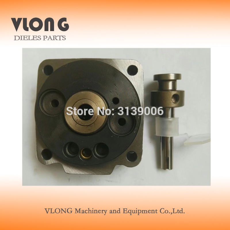
Cabezales 4/10R Head Rotor VE Pump 096400-1160 22140-5B270 1160 Hydraulic Head and Rotor 10MM 4-Cylinder Right for Fuel Injection Pump 096000-7090 Fits for Diesel Engine 1N-T 1Z
Cabezales Manufacturer MFR No.:096400-1160 , 22140-5B270 Stamping No. 1160 . || Application: Fit for Diesel Engine 1N-T 1Z . || Package: 1 Piece of Pump Head Rotor.Neutral Packing. || Compatible with Fuel Injection Pump: 096000-7090 || Notice:Please Check The No. Before Purchase Firstly,The Number Is Usually Stamped Around Its Body.If You Are Not Sure The No. Or You Have Any Question,Please Do Not Hesitate To Contact Us,We Will Reply You In Time.
Cabezales Manufacturer MFR No.:096400-1160 , 22140-5B270 Stamping No. 1160 . || Application: Fit for Diesel Engine 1N-T 1Z . || Package: 1 Piece of Pump Head Rotor.Neutral Packing. || Compatible with Fuel Injection Pump: 096000-7090 || Notice:Please Check The No. Before Purchase Firstly,The Number Is Usually Stamped Around Its Body.If You Are Not Sure The No. Or You Have Any Question,Please Do Not Hesitate To Contact Us,We Will Reply You In Time.

VE Pump Rotor Head 4/10R 096400-1160 Fit Intended For Engine 1N-T
Generic spare parts || autoparts || machinery parts || engine parts
Generic spare parts || autoparts || machinery parts || engine parts

$245.39
30 Nov 2023
KR: Adabus
Diesel Injection Rotor Head Or Pump Head Rotor 096400-1160
Generic Origin: Mainland China || Oem no.: 096400-1160
Generic Origin: Mainland China || Oem no.: 096400-1160
You can express buy:

USD 55.69
01-07-2019
01-07-2019
hot sale VE head rotor rotor head headrotor YK096-1160
USD 55.69
01-07-2019
01-07-2019
factory price,head rotorpump head 096400-1160,high quality dissel engine parts
USD 39
06-03-2019
06-03-2019
Head Rotor 096400-1160 VE4/10R Head VE Pump Parts
Include in #3:
Cross reference number
| Part num | Firm num | Firm | Name |
| 09640-01160 | HEAD SUB-ASSY, DIS | ||
| 22140-5B270 | TOYOTA | HEAD SUB-ASSY, DIS | |
| 22140-5B010 | TOYOTA | HEAD SUB-ASSY, DIS |
Information:
Timing Procedure for the Air Compressor
Follow the instructions below in order to properly time the air compressor on a C7 Engine. The air compressor must first be removed and then installed in order to properly time the air compressor.Removal Procedure for the Air Compressor
Do not disconnect the air lines until the air pressure in the system is at zero. If hose is disconnected under pressure it can cause personal injury.
Keep all parts clean from contaminants.Contaminants may cause rapid wear and shortened component life.
Care must be taken to ensure that fluids are contained during performance of inspection, maintenance, testing, adjusting and repair of the product. Be prepared to collect the fluid with suitable containers before opening any compartment or disassembling any component containing fluids.Refer to Special Publication, NENG2500, "Caterpillar Dealer Service Tool Catalog" for tools and supplies suitable to collect and contain fluids on Caterpillar products.Dispose of all fluids according to local regulations and mandates.
Ensure that the No. 1 cylinder is at the top center compression stroke. Refer to Testing and Adjusting, "Finding Top Center Position for No. 1 Piston".
Remove the air pressure from the air tank.
Drain the coolant from the cooling system into a suitable container for storage or for disposal. Refer to Operation and Maintenance Manual, "Cooling System Coolant (ELC) - Change".
Illustration 1 g01261253
Disconnect tube assembly (1), tube assembly (2), tube assembly (3), and hose assembly (4) .
Illustration 2 g01261257
Attach a suitable lifting device onto air compressor (5). The weight of air compressor (5) is approximately 32 kg (70 lb).
Illustration 3 g01261254
Illustration 4 g01271799
Remove bolts (8) and cover (9). Ensure that the timing mark on the crankshaft of the compressor is positioned between the timing marks on the housing for the compressor. Reinstall cover (9) and bolts (8). Remove bolts (6). Remove bracket (7) .
Illustration 5 g01261261
Remove bolts (10). Remove the air compressor and the O-ring seal from the engine.Installation Procedure for the Air Compressor
Ensure that the No. 1 cylinder is at the top center compression stroke. Refer to Testing and Adjusting, "Finding Top Center Position for No. 1 Piston".
Illustration 6 g01261257
Note: Check the O-ring seal for wear or for damage. If necessary, replace the O-ring seal.
Attach a suitable lifting device onto air compressor (5). The weight of air compressor (5) is approximately 32 kg (70 lb). Position the O-ring seal and air compressor (5) onto the engine.
Illustration 7 g01261261
Install bolts (10) .
Illustration 8 g01271799
Illustration 9 g01261254
Remove bolts (8) and cover (9). Ensure that the timing mark on the crankshaft of the compr