Information governor assy, tor
Rating:
Scheme ###:
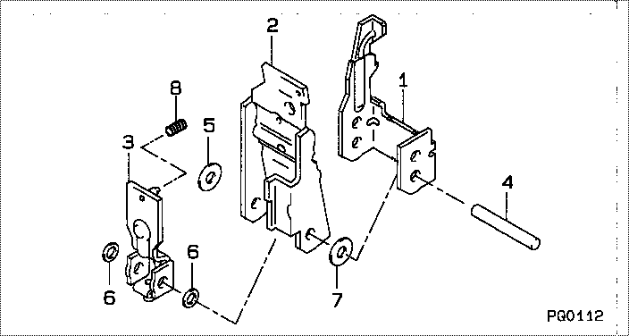
| 000. | [01] | 09627-02280 | GOVERNOR ASSY, TOR | 22350-78248-71 |
| 001. | [01] | 09627-10071 | LEVER, GUIDE | |
| 002. | [01] | 09628-50340 | LEVER SUB-ASSY, TE | |
| 003. | [01] | 09629-01230 | LEVER SUB-ASSY, TO | |
| 004. | [01] | 09627-20020 | PIN, LEVER SUPPORT | |
| 005. | [1C] | 09627-30170 | WASHER, GOVERNOR T | |
| 005. | [1C] | 09627-30160 | WASHER, GOVERNOR T | |
| 005. | [1C] | 09627-30020 | WASHER, GOVERNOR T | |
| 006. | [2C] | 09627-30050 | WASHER, GOVERNOR T | |
| 006. | [2C] | 09627-30100 | WASHER, GOVERNOR T | |
| 007. | [1C] | 09627-30210 | WASHER, GOVERNOR T | |
| 007. | [1C] | 09627-30200 | WASHER, GOVERNOR T | |
| 007. | [1C] | 09627-30030 | WASHER, GOVERNOR T | |
| 008. | [1C] | 09628-81230 | SPRING, DAMPER | |
| 008. | [1C] | 09628-81220 | SPRING, DAMPER | |
| 008. | [1C] | 09628-81210 | SPRING, DAMPER | |
| 008. | [1C] | 09628-81150 | SPRING, DAMPER | |
| 008. | [1C] | 09628-81140 | SPRING, DAMPER | |
| 008. | [1C] | 09628-81130 | SPRING, DAMPER | |
| 008. | [1C] | 09628-81120 | SPRING, DAMPER | |
| 008. | [1C] | 09628-81110 | SPRING, DAMPER | |
| 008. | [1C] | 09628-81100 | SPRING, DAMPER | |
| 008. | [1C] | 09628-81240 | SPRING, DAMPER |
Include in #3:
09627-02280
as GOVERNOR ASSY, TOR
Cross reference number
| Part num | Firm num | Firm | Name |
| 09627-02280 | 22350-7824 | GOVERNOR ASSY, TOR | |
| 22350-78248-71 | TICO | GOVERNOR ASSY, TOR |
Information:
Introduction
This Special Instruction provides information in order to prolong the life of the cutting bits on the PM-465 rotor. An additional spray nozzle was added to the left side of the chamber.Rework Procedure
Table 1
Required Parts
Quantity Part Number Description
1 211-8607 Tube
1 211-8604 Plate
1 1G-6699 Adapter
1 1G-8270 Nozzle Body
2 5D-1026 Hose Clamp
1000 mm (39 inch) 5P-1690 Hose
1 081-2963 Cap
1 081-2965 Seal
1 115-9969 Male Connector
1 115-9970 Male Connector
1 212-0911 Nozzle
Illustration 1 g00853436
(A) 573 mm (22.56 inches) (B) 102.5 mm (4 inches) (C) 150 mm (5.91 inches)
Remove 142-7461 Plate (1) from the chamber.
Relocate the 142-7461 Plate (1) .
The new location of the 142-7461 Plate (1) should measure 150 mm (5.91 inches) (C) from the top of the chamber. The center of the 142-7461 Plate should remain at 573 mm (22.56 inches) (A) .
Cut a slot in the left side of the chamber that is 40 mm (1.57 inch) by 85 mm (3.35 inch). The center of the slot should measure 102.5 mm (4 inches) from the top (B) of the chamber and 573 mm (22.56 inches) from the front (A) of the chamber. Refer to Illustration 1.
Illustration 2 g00853889
Weld the 211-8604 Plate (2) in the slot. The plate should be flush with the inside of the chamber. Face the open end of the plate downward in the slot.
Illustration 3 g00853468
Illustration 4 g00853890
(D) 20 mm (0.79 inch) (E) 8.5 mm (0.33 inch)
Weld a 211-8607 Tube (3) onto the side of the chamber. Position the bottom of the tube 20 mm (0.79 inch) (D) from the bottom of the slot and 8.5 mm (0.33 inch) (E) to the right of the slot. Refer to Illustration 4.
Illustration 5 g00853470
Remove hose assembly (4) from the nozzle (5) that is located near the left side of the chamber.
Replace connector (6) with 115-9970 Male Connector .
Illustration 6 g00863254
Use the following parts in order to assemble a new nozzle: 115-9969 Male Connector (7), 1G-6699 Adapter (8), 1G-8270 Nozzle Body (9), 212-0911 Nozzle (10), 081-2965 Seal (11) and 081-2963 Cap (12) .
Illustration 7 g00853509
Place the new nozzle assembly in tube (13) that is located on the side of the chamber.Note: The flat spray pattern of the nozzle should be parallel to the slot.
Connect the two nozzles with a 5P-1690 Hose . Use two 5D-1026 Hose Clamps in order to secure the hose to the nozzles.