Information governor assy, tor
Rating:
Scheme ###:
| 000. | [01] | 09627-01650 | GOVERNOR ASSY, TOR | |
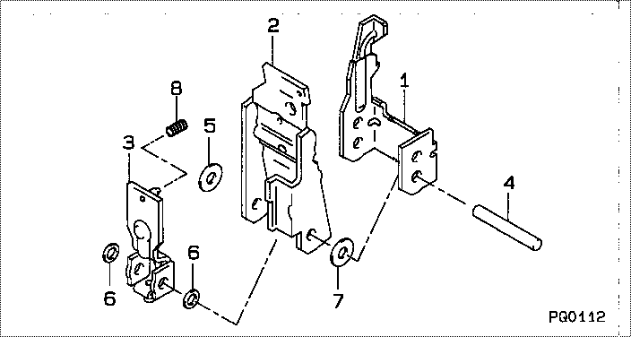
| 001. | [01] | 09627-10061 | LEVER, GUIDE | |
| 002. | [01] | 09628-50030 | LEVER SUB-ASSY, TE | |
| 003. | [01] | 09627-50031 | LEVER SUB-ASSY, SU | |
| 004. | [01] | 09627-20020 | PIN, LEVER SUPPORT | |
| 005. | [1C] | 09627-30170 | WASHER, GOVERNOR T | |
| 005. | [1C] | 09627-30160 | WASHER, GOVERNOR T | |
| 005. | [1C] | 09627-30020 | WASHER, GOVERNOR T | |
| 006. | [2C] | 09627-30110 | WASHER, GOVERNOR T | |
| 006. | [2C] | 09627-30180 | WASHER, GOVERNOR T | |
| 006. | [2C] | 09627-30190 | WASHER, GOVERNOR T | |
| 007. | [1C] | 09627-30210 | WASHER, GOVERNOR T | |
| 007. | [1C] | 09627-30200 | WASHER, GOVERNOR T | |
| 007. | [1C] | 09627-30030 | WASHER, GOVERNOR T | |
| 008. | [1C] | 09628-80291 | SPRING, DAMPER | |
| 008. | [1C] | 09628-80280 | SPRING, DAMPER | |
| 008. | [1C] | 09628-80250 | SPRING, DAMPER | |
| 008. | [1C] | 09628-80240 | SPRING, DAMPER | |
| 008. | [1C] | 09628-80230 | SPRING, DAMPER | |
| 008. | [1C] | 09628-80220 | SPRING, DAMPER | |
| 008. | [1C] | 09628-80200 | SPRING, DAMPER | |
| 008. | [1C] | 09628-80180 | SPRING, DAMPER | |
| 008. | [1C] | 09628-80170 | SPRING, DAMPER | |
| 008. | [1C] | 09628-80160 | SPRING, DAMPER | |
| 008. | [1C] | 09628-80030 | SPRING, DAMPER | |
| 008. | [1C] | 09628-80020 | SPRING, DAMPER | |
| 008. | [1C] | 09628-80301 | SPRING, DAMPER |
Include in #3:
Cross reference number
| Part num | Firm num | Firm | Name |
| 09627-01650 | GOVERNOR ASSY, TOR |
Information:
Introduction
This special instruction provides the rework procedure for the replacement of the fuel transfer pump that is located on the HEUI pump. The procedure calls for a temporary service bolt that is used during the removal of the fuel transfer pump in order to prevent the body of HEUI pump from separating. Once the fuel transfer pump has been reinstalled onto the HEUI pump, the service bolt is then removed.
The correct procedures and tooling specifications must always be used. Failure to follow any of the procedures may result in damage, malfunction, or possible engine failure.
Keep all parts clean from contaminants.Contaminants may cause rapid wear and shortened component life.
Care must be taken to ensure that fluids are contained during performance of inspection, maintenance, testing, adjusting and repair of the product. Be prepared to collect the fluid with suitable containers before opening any compartment or disassembling any component containing fluids.Refer to Special Publication, NENG2500, "Caterpillar Tools and Shop Products Guide" for tools and supplies suitable to collect and contain fluids on Caterpillar products.Dispose of all fluids according to local regulations and mandates.
Table 1
Required Tools
Callout Part Number Description
A 193-9199 T27 Torx bit (1)
B 194-3536 T40 Torx bit (1)
C 6 mm Hex Key Wrench
Flat head screwdriver
Torque Wrench (in lb)
Torque Wrench (ft lb)
1U-6396 O-Ring Assembly Compound
( 1 ) Or EquivalentNote: The 178-2357 Fuel Transfer Pump Gp is required for replacement of the fuel transfer pump. Refer to Table 2 for a list of the components that are needed.
Table 2
Required Components
Callout Part Number Description Qty
5 227-5904 O-Ring Seal 1
9 256-0302 Bolt 1
10 239-2402 Seal 2
11 179-8128 Seal 1
12 185-3241 O-Ring Seal 1 Removal of the HEUI Pump
Prior to removing the HEUI pump, wash the engine in order to remove all of the dirt from the area that surrounds the HEUI pump. Remove the HEUI pump. Refer to Disassembly and Assembly, "Unit Injector Hydraulic Pump - Remove" for the correct procedure.Note: Do not allow any debris to enter the HEUI pump or the HEUI pump parts. Allowing debris to enter the HEUI pump will cause pump failure.Note: Do not attempt to perform this rework procedure while the HEUI pump is still on the engine.Removing the Fuel Transfer Pump from the HEUI Pump
Use a vise (3) in order to secure the HEUI pump (1) vertically with the drive gear (4) on the bottom. Make sure that the vise has jaws that are made from aluminum or some other soft material. Do not clamp on the gear or the front mounting flange.