Information cover sub-assy, ti

Rating:
Scheme ###:
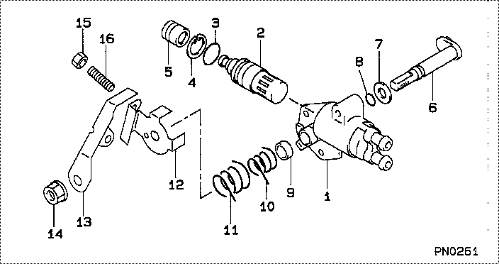
| 000. | [01] | 09621-00931 | COVER SUB-ASSY, TI | 22790-6D480 |
| 001. | [01] | 09621-80092 | COVER, TIMER | |
| 002. | [01] | 09648-50110 | THERMO-ELEMENT SUB | |
| 003. | [01] | 09604-90280 | O-RING | |
| 004. | [01] | 90567-28001 | RING, HOLE SNAP | |
| 005. | [01] | 09007-80121 | COVER | |
| 006. | [01] | 09645-10441 | SHAFT SUB-ASSY, AD | |
| 007. | [01] | 09627-30140 | WASHER, GOVERNOR T | 22378-64010 |
| 008. | [01] | 09604-90300 | O-RING | 22193-54770 |
| 008. | [01] | 94914-02910 | O-RING | 90099-14048 |
| 009. | [01] | 94919-25581 | COLLAR, STEEL | |
| 010. | [01] | 09644-40060 | SPRING, RETURN | |
| 011. | [01] | 09644-40070 | SPRING, RETURN | |
| 012. | [01] | 09644-50042 | GUIDE, RETURN SPRI | |
| 013. | [01] | 09643-61611 | LEVER, ADJUSTING | |
| 014. | [01] | 94905-63320 | NUT | |
| 014. | [01] | 92156-08081 | NUT, FLANGE | 90092-60001 |
| 015. | [01] | 91160-05041 | NUT, HEXAGON | 94115-40500 |
| 016. | [01] | 09266-40100 | SCREW, LEVER STOP |
Cross reference number
| Part num | Firm num | Firm | Name |
| 09621-00930 | COVER SUB-ASSY, TI | ||
| 22790-6D480-000 | DAIHATSU | COVER SUB-ASSY, TI | |
| 22790-6D480 | TOYOTA | COVER SUB-ASSY, TI |
Information:
System Operation
The SLC 5/04 diagnostic indicators are located on the front of the following components: Power Supply, CPU and I/O Modules.The diagnostic indicators help trace the source of the fault. Faults can be found in the following components: Input devices, Output devices, Wiring and The controller.The "FLT" LED is illuminated and the outputs of the controller are de-energized. The power to a chassis is lost.The red "FLT" LED is illuminated. There is a fatal error. A fatal error indicates that the processor is not communicating.The red "FLT" LED is flashing during operation. The processor detects a major fault. The fault is in the processor expansion chassis or the fault is in the memory.The green "RS232" LED is illuminated in the DH+ mode. The communications active bit (S:17) is set in the "System Status" file. The processor is communicating on the network.The green "RS232" LED is flashing in the DH+ mode. The processor cannot establish communication because there are no active nodes on the network.The "RS232" LED is extinguished in the DH+ mode. A fatal error is present.
Illustration 1 g00563574
Diagram of the LED indicators
Illustration 2 g00563507
Functional Test
Check the electrical connectors and check the wiring.
Bodily contact with electrical potential can cause bodily injury or death.To avoid the possibility of injury or death, ensure that the main power supply has been disconnected before performing any maintenance or removing any modules.
Disconnect the power supply.
Check the electrical connectors and check the wiring for damage or bad connections.
Verify that all modules are properly seated.
Verify the status of the LED on the SLC 5/04.The results of the preceding procedure are in the following list:
All of the components are fully installed. All of the components are free of corrosion. All of the components are free of damage. All of the modules are properly seated. Proceed to 2.
The components are not fully installed. The components are not free of corrosion. The components are damaged. All of the modules are not properly seated. Repair the component. Verify that the repair resolves the problem. STOP.
Check the line voltage.
Reconnect the power supply.
Measure the line voltage at the terminals.
Verify the voltage of the power supply. The power supply voltage should be measured between 21.0 VDC and 28.0 VDC.The results of the preceding procedure are in the following list:
The line voltage is in the range. Proceed to 3.
The line voltage is out of the range. Refer to Troubleshooting, "System Power". Stop.
Cycle the power.
Secure power to the PLC.
Energize the PLC.The results of the preceding procedure are in the following list:
No errors are displayed on the LED indicators. Stop.
Errors are displayed on the LED indicators. Refer to Maintenance Procedure, "Processor - Replace". Stop.