Information pump assy, injecti
Nozzle:
0935003240
Rating:
KIT List:
| Pump assy, injecti | 0960100021 0960100541 |
Components :
| 001. | PUMP ASSY, INJECTI | 09600-02320 |
| 002. | RING SUB-ASSY, ROL | 09618-00050 |
| 003. | COVER SUB-ASSY, TI | 09621-00280 |
| 004. | GOVERNOR ASSY, TOR | 09627-00100 |
| 005. | SHIM, PLUNGER ADJU | 09640-60020 |
Scheme ###:
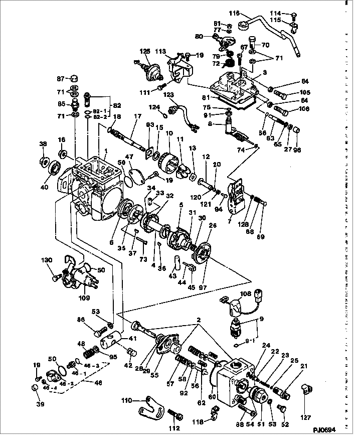
| 000. | [01] | 09600-02320 | PUMP ASSY, INJECTI | 22100-64770 |
| 001. | [01] | 09611-00241 | HOUSING SUB-ASSY, | 22101-64020 |
| 002. | [01] | 09640-00241 | HEAD SUB-ASSY, DIS | 22140-64400 |
| 003. | [01] | 09644-00500 | COVER SUB-ASSY, GO | 22703-54450 |
| 004. | [01] | 09612-10070 | SHAFT, DRIVE | 22170-54180 |
| 005. | [01] | 09618-00050 | RING SUB-ASSY, ROL | 22108-54180 |
| 006. | [01] | 09614-00030 | PUMP SUB-ASSY, FUE | 22505-54010 |
| 007. | [01] | 09627-00100 | GOVERNOR ASSY, TOR | 22350-64010 |
| 008. | [01] | 09646-00340 | SHAFT SUB-ASSY, SP | 22302-64740 |
| 009. | [01] | 09603-00070 | SOLENOID ASSY, FUE | 22390-54110 |
| 009-001. | [01] | 09604-90030 | O-RING | 22193-64010 |
| 010. | [01] | 09626-00050 | HOLDER SUB-ASSY, F | 22741-54020 |
| 011. | [04] | 09626-30030 | FLYWEIGHT, DISTRIB | 22745-54010 |
| 012. | [01] | 09625-20280 | SLEEVE, GOVERNOR | 22316-54351 |
| 013. | [01] | 09626-50040 | WASHER, FLYWEIGHT | 22753-54290 |
| 013. | [01] | 09626-50030 | WASHER, FLYWEIGHT | 22753-54020 |
| 015. | [01] | 09626-50020 | WASHER, FLYWEIGHT | 22753-54010 |
| 016. | [01] | 09625-40050 | NUT, GOVERNOR SHAF | 22722-54470 |
| 017. | [01] | 09625-00030 | SHAFT SUB-ASSY, GO | 22380-54020 |
| 018. | [01] | 94914-02930 | O-RING | 90099-14049 |
| 020. | [01] | 09625-50020 | RING, GOVERNOR SLE | 22147-54290 |
| 021. | [04] | 09643-00010 | VALVE SUB-ASSY, SN | 22190-54170 |
| 022. | [04] | 09642-00120 | VALVE SUB-ASSY, DI | 22104-64010 |
| 023. | [04] | 09642-70010 | SPRING, DELIVERY V | 22148-54010 |
| 024. | [04] | 09642-60020 | GASKET, DELIVERY V | 22149-54010 |
| 025. | [04] | 09642-80020 | SEAT, DELIVERY VAL | 22141-54250 |
| 026. | [01] | 09623-00090 | CAMPLATE SUB-ASSY, | 22130-64010 |
| 027. | [01] | 94905-30200 | NUT, HEXAGON, W/ H | 90099-05140 |
| 028. | [01] | 09624-50020 | PLATE, PLUNGER, LW | 22163-54010 |
| 029. | [01] | 09624-40040 | PLATE, PLUNGER, UP | 22162-54010 |
| 030. | [01] | 09622-40040 | SPRING, COUPLING | 22659-64150 |
| 031. | [01] | 09622-20020 | COUPLING | 22632-54010 |
| 032. | [01] | 09612-40030 | GEAR, GOVERNOR DRI | 22341-54010 |
| 033. | [02] | 09612-60020 | JOINT, RUBBER | 22169-54180 |
| 034. | [01] | 09612-50010 | WASHER, DRIVE SHAF | 22161-54010 |
| 035. | [01] | 09614-70040 | COVER, FEED PUMP | 22511-54020 |
| 036. | [01] | 94913-00260 | KEY, WOODRUFF | 90099-13017 |
| 037. | [01] | 94913-00300 | KEY, WOODRUFF | 90099-13018 |
| 038. | [01] | 94905-62390 | NUT | 90099-05166 |
| 039. | [01] | 09644-80240 | COLLAR, SMOKE SET | 22749-64740 |
| 040. | [01] | 09603-90040 | SEAL, 0IL | 22544-64740 |
| 041. | [01] | 09620-10380 | PISTON, TIMER | 22654-64740 |
| 042. | [01] | 09621-30020 | SUB-PISTON, TIMER | 22657-54010 |
| 043. | [01] | 09620-50020 | PIN, TIMER SLIDE | 22655-54010 |
| 044. | [01] | 09621-60020 | STOPPER, TIMER SLI | 22658-54010 |
| 045. | [01] | 09621-10050 | CLIP, TIMER | 22656-54010 |
| 046. | [01] | 09621-00230 | COVER SUB-ASSY, TI | 22790-54450 |
| 046-001. | [01] | 09621-60040 | STOPPER, TIMER SLI | 22658-54450 |
| 046-002. | [01] | 09621-80230 | COVER, TIMER | 22612-54450 |
| 046-003. | [01] | 90801-10150 | O-RING | 90096-80004 |
| 046-003. | [01] | 09604-90190 | O-RING | 22193-64750 |
| 046-004. | [01] | 94905-04670 | NUT, HEXAGON | 90099-05184 |
| 047. | [01] | 09621-80020 | COVER, TIMER | 22612-54010 |
| 048. | [1C] | 09620-80120 | SPRING, TIMER, OUT | 22615-64010 |
| 048. | [1C] | 09620-80161 | SPRING, TIMER, OUT | 22615-54180 |
| 048. | [1C] | 09620-80180 | SPRING, TIMER, OUT | 22615-54413 |
| 050. | [03] | 94914-02960 | O-RING | 90099-14051 |
| 051. | [01] | 09641-70040 | PLUG, DISTRIBUTIVE | 22176-54020 |
| 052. | [01] | 09641-80020 | BOLT, DISTRIBUTIVE | 22128-54010 |
| 053. | [03] | 09642-60030 | GASKET, DELIVERY V | 22149-56200 |
| 054. | [01] | 94914-02970 | O-RING | 90099-14052 |
| 055. | [01] | 09624-70010 | SHEET, PLUNGER SPR | 22145-54010 |
| 056. | [02] | 09623-70010 | GUIDE SUB-ASSY, PL | 22192-54010 |
| 057. | [02] | 09623-60030 | SPRING, PLUNGER | 22144-54180 |
| 058. | [02] | 09624-60010 | SHEET, PLUNGER SPR | 22143-54010 |
| 060. | [01] | 94914-02980 | O-RING | 90099-14053 |
| 062. | [02] | 09627-90010 | SPRING, LEVER SUPP | 22314-54010 |
| 063. | [01] | 09644-70040 | SCREW, SMOKE SET | 22776-54110 |
| 066. | [01] | 94914-02900 | O-RING | 90099-14047 |
| 067. | [04] | 09644-90020 | BOLT, SOCKET | 22395-54010 |
| 068. | [01] | 09628-90110 | SPRING, GOVERNOR I | 22317-64030 |
| 069. | [01] | 09626-70060 | SHEET, GOVERNOR SP | 22369-54080 |
| 070. | [01] | 09602-00030 | SCREW SUB-ASSY, OV | 22160-64010 |
| 071. | [05] | 09024-10010 | WASHER, AIR BLEEDE | 22119-77020 |
| 072. | [01] | 09644-40091 | SPRING, RETURN | 22322-64010 |
| 073. | [02] | 94900-20420 | SCREW, COUNTERSUNK | 90099-00723 |
| 074. | [01] | 09645-70010 | WASHER, SNAP | 22365-54040 |
| 075. | [01] | 94914-02910 | O-RING | 90099-14048 |
| 079. | [01] | 09644-40490 | SPRING, RETURN | 22322-64740 |
| 080. | [1C] | 09643-51490 | LEVER SUB-ASSY, AD | 22701-64740 |
| 080. | [1C] | 09643-51500 | LEVER SUB-ASSY, AD | 22701-64750 |
| 081. | [01] | 09644-60093 | GASKET, GOVERNOR C | 22774-54010 |
| 082. | [01] | 09616-00030 | VALVE SUB-ASSY, RE | 22180-54010 |
| 082-001. | [01] | 09604-90180 | O-RING | 22193-54561 |
| 082-002. | [01] | 94914-02920 | O-RING | 90099-14080 |
| 084. | [01] | 09634-20010 | NUT, LOCK | 22775-77121 |
| 085. | [01] | 94918-00770 | SCREW, HOLLOW | 90099-18022 |
| 086. | [02] | 09626-90020 | BOLT, GOVERNOR LIN | 22739-54020 |
| 087. | [01] | 94905-50300 | NUT, CAP | 90099-05161 |
| 088. | [04] | 09644-90070 | BOLT, SOCKET | 22395-58200 |
| 091. | [01] | 09627-30140 | WASHER, GOVERNOR T | 22378-64010 |
| 092. | [2C] | 09624-80110 | SHIM, PLUNGER SPRI | 22182-17013 |
| 092. | [2C] | 09624-80100 | SHIM, PLUNGER SPRI | 22182-17012 |
| 092. | [2C] | 09624-80090 | SHIM, PLUNGER SPRI | 22182-17011 |
| 092. | [2C] | 09624-80080 | SHIM, PLUNGER SPRI | 22182-17010 |
| 092. | [2C] | 09624-80070 | SHIM, PLUNGER SPRI | 22188-54010 |
| 092. | [2C] | 09624-80060 | SHIM, PLUNGER SPRI | 22187-54010 |
| 092. | [2C] | 09624-80050 | SHIM, PLUNGER SPRI | 22186-54010 |
| 092. | [2C] | 09624-80040 | SHIM, PLUNGER SPRI | 22185-54010 |
| 092. | [2C] | 09624-80030 | SHIM, PLUNGER SPRI | 22184-54010 |
| 092. | [2C] | 09624-80020 | SHIM, PLUNGER SPRI | 22183-54010 |
| 092. | [2C] | 09624-80010 | SHIM, PLUNGER SPRI | 22182-54010 |
| 093. | [1C] | 09626-60170 | WASHER, GOVERNOR G | |
| 093. | [1C] | 09626-60160 | WASHER, GOVERNOR G | |
| 093. | [1C] | 09626-60150 | WASHER, GOVERNOR G | |
| 093. | [1C] | 09626-60140 | WASHER, GOVERNOR G | 22717-54010 |
| 093. | [1C] | 09626-60130 | WASHER, GOVERNOR G | 22716-54010 |
| 093. | [1C] | 09626-60120 | WASHER, GOVERNOR G | 22715-54010 |
| 093. | [1C] | 09626-60110 | WASHER, GOVERNOR G | 22714-54010 |
| 093. | [1C] | 09626-60100 | WASHER, GOVERNOR G | 22713-54010 |
| 094. | [1C] | 09625-60440 | PLUG, GOVERNOR SLE | 22787-54027 |
| 094. | [1C] | 09625-60430 | PLUG, GOVERNOR SLE | 22787-54026 |
| 094. | [1C] | 09625-60420 | PLUG, GOVERNOR SLE | 22787-64643 |
| 094. | [1C] | 09625-60410 | PLUG, GOVERNOR SLE | 22787-64642 |
| 094. | [1C] | 09625-60400 | PLUG, GOVERNOR SLE | 22787-64641 |
| 095. | [01] | 09621-40050 | WASHER, TIMER SENS | 22625-54272 |
| 097. | [1C] | 09640-60520 | SHIM, PLUNGER ADJU | 22179-54020 |
| 097. | [1C] | 09640-60470 | SHIM, PLUNGER ADJU | 22179-54019 |
| 097. | [1C] | 09640-60420 | SHIM, PLUNGER ADJU | 22179-54018 |
| 097. | [1C] | 09640-60370 | SHIM, PLUNGER ADJU | 22179-54017 |
| 097. | [1C] | 09640-60320 | SHIM, PLUNGER ADJU | 22179-54016 |
| 097. | [1C] | 09640-60270 | SHIM, PLUNGER ADJU | 22179-54015 |
| 097. | [1C] | 09640-60220 | SHIM, PLUNGER ADJU | 22179-54014 |
| 097. | [1C] | 09640-60170 | SHIM, PLUNGER ADJU | 22179-54013 |
| 097. | [1C] | 09640-60120 | SHIM, PLUNGER ADJU | 22179-54012 |
| 097. | [1C] | 09640-60070 | SHIM, PLUNGER ADJU | 22179-54011 |
| 097. | [1C] | 09640-60020 | SHIM, PLUNGER ADJU | 22179-54010 |
| 105. | [01] | 94904-50190 | BOLT, HEXAGON, W/ | 90099-04946 |
| 106. | [01] | 94904-50180 | BOLT, HEXAGON, W/ | 90099-04576 |
| 108. | [01] | 09604-50100 | WIRE SUB-ASSY | 22751-64010 |
| 109. | [01] | 09621-00280 | COVER SUB-ASSY, TI | 22790-64740 |
| 110. | [01] | 09643-80110 | BRACKET, IDLE UP | 22178-64010 |
| 111. | [01] | 09644-90070 | BOLT, SOCKET | 22395-58200 |
| 111. | [01] | 94904-72220 | BOLT, W/WASHER | 90099-04959 |
| 112. | [01] | 91418-08201 | BOLT, W/WASHER | 91611-60820 |
| 112. | [01] | 09644-90140 | BOLT, SOCKET | 22395-56350 |
| 113. | [01] | 09647-00060 | IDLE UP SUB-ASSY | 22305-64010 |
| 114. | [01] | 91510-06121 | BOLT, W/WASHER | 93381-16012 |
| 114. | [01] | 09644-90130 | BOLT, SOCKET | 22395-54263 |
| 115. | [01] | 09602-90251 | CLIP, CONNECTOR SU | 22172-64150 |
| 116. | [01] | 09221-80010 | NIPPLE SUB-ASSY, S | 22548-64150 |
| 118. | [01] | 09602-90110 | CLIP, CONNECTOR SU | 22172-64040 |
| 120. | [01] | 90577-02000 | E-RING | 90096-90024 |
| 121. | [01] | 94910-02860 | BEARING, BALL | 90099-10148 |
| 123. | [01] | 07630-00241 | PICKUP ASSY, TACHO | 83180-12010 |
| 123. | [01] | 07630-01710 | PICKUP ASSY, TACHO | |
| 124. | [01] | 09604-90030 | O-RING | 22193-64010 |
| 125. | [01] | 09647-20020 | ACTUATOR SET, IDLE | 88031-30070 |
| 127. | [01] | 09602-90350 | CLIP, CONNECTOR SU | 22172-64230 |
| 128. | [01] | 09627-30220 | WASHER, GOVERNOR T | 22378-6A250 |
| 130. | [01] | 91510-06121 | BOLT, W/WASHER | 93381-16012 |
| 130. | [01] | 09644-90100 | BOLT, SOCKET | 22395-56352 |
Include in #3:
09600-02320
as PUMP ASSY, INJECTI
Cross reference number
| Part num | Firm num | Firm | Name |
| 09600-02320 | 22100-6477 | PUMP ASSY, INJECTI | |
| 22100-64770 | TOYOTA | PUMP ASSY, INJECTI |
Information:
System Operation
The SLC 5/04 diagnostic indicators are located on the front of the following components: Power Supply, CPU and I/O Modules.The diagnostic indicators help trace the source of the fault. Faults can be found in the following components: Input devices, Output devices, Wiring and The controller.The thermocouple module has five LED indicators. Four of the LED indicators are "Channel Status" indicators. The "Channel Status" indicators are numbered according to the channel. One of the LED indicators is a "Module Status" indicator.Diagnostics are displayed on the "Module Status" LED indicator. Operating errors are displayed on the "Module Status" LED indicator. Problems may be detected during powerup or problems may be detected during operation. When an error occurs, the module will not communicate with the processor. The channel is disabled and the data is cleared.
Illustration 1 g00563417
Diagram of the LED indicators
Illustration 2 g00563392
Diagram of the LED indicators
Illustration 3 g00563575
Diagram of the RTD module
Illustration 4 g00563579
Schematic of the RTD moduleFunctional Test
The "Module Status" LED is on. The module is operating normally. Stop.
The "Channel Status" LED is on. The module is operating normally. Stop.
The "Module Status" LED is off. The module is in a fault condition. Proceed to 6.
The "Channel Status" LED is off. The channel is not enabled. This is normal if the sensor is not wired.
The "Channel Status" LED is blinking. The module is in a fault condition. Proceed to 10.
Check the electrical connectors and check the wiring.
Bodily contact with electrical potential can cause bodily injury or death.To avoid the possibility of injury or death, ensure that the main power supply has been disconnected before performing any maintenance or removing any modules.
Disconnect the power supply.
Check the electrical connectors and check the wiring for damage or bad connections.
Verify that all modules are properly seated.
Verify the status of the LED on the SLC 5/04.The results of the preceding procedure are in the following list:
All of the components are fully installed. All of the components are free of corrosion. All of the components are free of damage. All of the modules are properly seated. Proceed to 7.
The components are not fully installed. The components are not free of corrosion. The components are damaged. All of the modules are not properly seated. Repair the component. Verify that the repair resolves the problem. STOP.
Check the LED indicator on the module.
Connect the power supply.
Cycle the power to the module.The results of the preceding procedure are in the following list:
No errors are displayed on the LED indicators. Stop.
Errors are displayed on the LED indicators. Proceed to 8.
Check the module for a fault.
Bodily contact with electrical potential can cause bodily injury or death.To avoid the possibility of injury or death, ensure that the main power supply has been disconnected before performing any maintenance or removing any modules.
To avoid potential damage to the processor, handle all modules by the ends of the carrier or edges of the plastic housing. Skin oil or dirt can corrode metallic surfaces, inhibiting electrical contact.
Disconnect the power supply.
Remove the module from the chassis.Reference: Maintenance Procedure, "Input Module and