Information pump assy, injecti
Nozzle:
0935002120
Rating:
KIT List:
| Pump assy, injecti | 0960100021 0960100541 |
Components :
| 001. | PUMP ASSY, INJECTI | 09600-00520 |
| 002. | RING SUB-ASSY, ROL | 09618-00020 |
| 003. | RING SUB-ASSY, ROL | 09618-00050 |
| 004. | GOVERNOR ASSY, TOR | 09627-00090 |
| 005. | SHIM, PLUNGER ADJU | 09640-60020 |
Scheme ###:
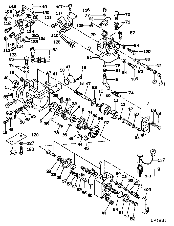
| 000. | [01] | 09600-00522 | PUMP ASSY, INJECTI | S503 13 800A |
| 001. | [01] | 09611-00141 | HOUSING SUB-ASSY, | S503 24 010 |
| 002. | [01] | 09640-00111 | HEAD SUB-ASSY, DIS | S501 24 100 |
| 002. | [01] | 09640-00510 | HEAD SUB-ASSY, DIS | |
| 002. | [01] | 09640-01180 | HEAD SUB-ASSY, DIS | |
| 003. | [01] | 09644-00120 | COVER SUB-ASSY, GO | S501 24 161 |
| 004. | [01] | 09612-10020 | SHAFT, DRIVE | |
| 004. | [01] | 09612-10050 | SHAFT, DRIVE | S501 24 031 |
| 005. | [01] | 09618-00020 | RING SUB-ASSY, ROL | S501 24 040 |
| 005. | [01] | 09618-00050 | RING SUB-ASSY, ROL | S503 24 040 |
| 006. | [01] | 09614-00020 | PUMP SUB-ASSY, FUE | S501 24 020 |
| 007. | [01] | 09627-00090 | GOVERNOR ASSY, TOR | S501 24 200 |
| 008. | [01] | 09645-00050 | SHAFT SUB-ASSY, GO | S501 24 170 |
| 009. | [01] | 09601-00700 | OVER-HAUL KIT, DIS | |
| 009-001. | [01] | 09604-90030 | O-RING | S501 24 303 |
| 009-001. | [01] | 09604-90350 | O-RING | S5A1 13 VJ7 |
| 010. | [01] | 09626-00031 | HOLDER SUB-ASSY, F | |
| 011. | [04] | 09626-30030 | FLYWEIGHT, DISTRIB | S501 24 232 |
| 012. | [01] | 09625-20040 | SLEEVE, GOVERNOR | S501 24 234 |
| 012. | [01] | 09625-20230 | SLEEVE, GOVERNOR | |
| 013. | [01] | 09626-50040 | WASHER, FLYWEIGHT | RF10 24 233 |
| 013. | [01] | 09626-50030 | WASHER, FLYWEIGHT | S501 24 233 |
| 015. | [01] | 09626-50020 | WASHER, FLYWEIGHT | S501 24 229 |
| 016. | [01] | 09625-40010 | NUT, GOVERNOR SHAF | S501 24 221 |
| 017. | [01] | 09625-10020 | SHAFT, GOVERNOR MA | S501 24 222 |
| 018. | [01] | 94914-02930 | O-RING | S501 24 223 |
| 019. | [04] | 91518-06161 | BOLT, W/WASHER | S501 24 058 |
| 020. | [01] | 09625-50010 | RING, GOVERNOR SLE | S501 24 235 |
| 021. | [04] | 09642-50030 | HOLDER, DELIVERY V | |
| 022. | [04] | 09642-00100 | VALVE SUB-ASSY, DI | S501 24 140 |
| 023. | [04] | 09642-70010 | SPRING, DELIVERY V | S501 24 142 |
| 024. | [04] | 09642-60020 | GASKET, DELIVERY V | S501 24 141 |
| 025. | [04] | 09642-80010 | SEAT, DELIVERY VAL | S501 24 143 |
| 026. | [01] | 09623-00070 | CAMPLATE SUB-ASSY, | S501 24 049 |
| 026. | [01] | 09623-00140 | CAMPLATE SUB-ASSY, | |
| 027. | [01] | 94905-30200 | NUT, HEXAGON, W/ H | S501 24 195 |
| 028. | [01] | 09624-50020 | PLATE, PLUNGER, LW | S501 24 071 |
| 029. | [01] | 09624-40040 | PLATE, PLUNGER, UP | S501 24 072 |
| 030. | [01] | 09622-40040 | SPRING, COUPLING | |
| 030. | [01] | 09622-40020 | SPRING, COUPLING | S501 24 048 |
| 031. | [01] | 09622-20020 | COUPLING | S501 24 047 |
| 032. | [01] | 09612-40030 | GEAR, GOVERNOR DRI | S501 24 035 |
| 033. | [02] | 09612-60020 | JOINT, RUBBER | |
| 033. | [02] | 09612-60010 | JOINT, RUBBER | S501 24 034 |
| 034. | [01] | 09612-50010 | WASHER, DRIVE SHAF | S501 24 036 |
| 035. | [01] | 09614-70040 | COVER, FEED PUMP | S501 24 023 |
| 036. | [01] | 94913-00260 | KEY, WOODRUFF | S501 24 032 |
| 040. | [01] | 09603-90020 | SEAL, 0IL | S501 24 012 |
| 041. | [01] | 09620-10060 | PISTON, TIMER | S501 24 052 |
| 042. | [01] | 09621-30020 | SUB-PISTON, TIMER | S501 24 053 |
| 043. | [01] | 09620-50020 | PIN, TIMER SLIDE | S501 24 044 |
| 044. | [01] | 09621-60020 | STOPPER, TIMER SLI | S501 24 045 |
| 045. | [01] | 09621-10050 | CLIP, TIMER | S501 24 046 |
| 046. | [01] | 09621-80040 | COVER, TIMER | S501 24 057 |
| 047. | [01] | 09621-80020 | COVER, TIMER | S501 24 059 |
| 048. | [1C] | 09620-80100 | SPRING, TIMER, OUT | S501 24 055 |
| 048. | [1C] | 09620-80130 | SPRING, TIMER, OUT | S501 24 062 |
| 048. | [1C] | 09620-80140 | SPRING, TIMER, OUT | S501 24 061 |
| 050. | [02] | 09604-90400 | O-RING | |
| 050. | [02] | 94914-05820 | O-RING | |
| 050. | [02] | 94914-02960 | O-RING | S501 24 051 |
| 051. | [01] | 09641-70040 | PLUG, DISTRIBUTIVE | S501 24 151 |
| 052. | [01] | 09641-80020 | BOLT, DISTRIBUTIVE | S501 24 152 |
| 053. | [03] | 94901-81020 | WASHER, COPPER PLA | S501 24 154 |
| 054. | [01] | 94914-02970 | O-RING | S501 24 153 |
| 055. | [01] | 09624-70010 | SHEET, PLUNGER SPR | S501 24 073 |
| 056. | [02] | 09623-70010 | GUIDE SUB-ASSY, PL | S501 24 076 |
| 057. | [02] | 09623-60020 | SPRING, PLUNGER | |
| 057. | [02] | 09623-60030 | SPRING, PLUNGER | S501 24 074 |
| 058. | [02] | 09624-60010 | SHEET, PLUNGER SPR | S501 24 075 |
| 060. | [01] | 94914-02980 | O-RING | S501 24 105 |
| 062. | [02] | 09627-90010 | SPRING, LEVER SUPP | S501 24 078 |
| 063. | [01] | 09644-70030 | SCREW, SMOKE SET | |
| 063. | [01] | 09644-70040 | SCREW, SMOKE SET | S501 24 191 |
| 064. | [01] | 09634-20010 | NUT, LOCK | S501 24 182 |
| 065. | [01] | 90200-08211 | WASHER, PLATE | S501 24 194 |
| 066. | [01] | 09604-90470 | O-RING | S501 24 196 |
| 067. | [04] | 09644-90020 | BOLT, SOCKET | S501 24 163 |
| 068. | [01] | 09628-90020 | SPRING, GOVERNOR I | S501 24 265 |
| 069. | [01] | 09626-70030 | SHEET, GOVERNOR SP | S501 24 261 |
| 070. | [01] | 09602-00010 | SCREW SUB-ASSY, OV | S501 24 280 |
| 071. | [04] | 09024-10010 | WASHER, AIR BLEEDE | S501 24 283 |
| 073. | [02] | 94900-20420 | SCREW, COUNTERSUNK | S501 24 024 |
| 074. | [01] | 09626-10111 | SPRING, SPEED CONT | S501 24 275 |
| 074. | [01] | 09626-10140 | SPRING, SPEED CONT | |
| 075. | [02] | 94914-02910 | O-RING | S501 24 171 |
| 077. | [02] | 90258-06001 | WASHER, SPRING | 0107 18 604 |
| 079. | [01] | 09644-40042 | SPRING, RETURN | S501 24 177 |
| 080. | [1C] | 09643-60120 | LEVER, ADJUSTING | S501 24 173 |
| 080. | [1C] | 09643-60130 | LEVER, ADJUSTING | S501 24 174 |
| 080. | [1C] | 09643-61440 | LEVER, ADJUSTING | |
| 080. | [1C] | 09643-61450 | LEVER, ADJUSTING | |
| 081. | [01] | 09644-60092 | GASKET, GOVERNOR C | S501 24 162 |
| 082. | [01] | 09616-00050 | VALVE SUB-ASSY, RE | S501 24 270 |
| 082-001. | [01] | 09604-90180 | O-RING | |
| 082-002. | [01] | 94914-02920 | O-RING | S501 24 272 |
| 084. | [01] | 94905-04080 | NUT, HEXAGON | S501 24 181 |
| 085. | [01] | 94918-00131 | SCREW, HOLLOW | |
| 086. | [02] | 09626-90020 | BOLT, GOVERNOR LIN | S501 24 201 |
| 088. | [04] | 09644-90070 | BOLT, SOCKET | |
| 091. | [02] | 09627-30060 | WASHER, GOVERNOR T | S501 24 172 |
| 092. | [ C] | 09624-80110 | SHIM, PLUNGER SPRI | S501 24 092 |
| 092. | [ C] | 09624-80100 | SHIM, PLUNGER SPRI | S501 24 091 |
| 092. | [ C] | 09624-80090 | SHIM, PLUNGER SPRI | S501 24 089 |
| 092. | [ C] | 09624-80080 | SHIM, PLUNGER SPRI | S501 24 088 |
| 092. | [ C] | 09624-80070 | SHIM, PLUNGER SPRI | S501 24 087 |
| 092. | [ C] | 09624-80060 | SHIM, PLUNGER SPRI | S501 24 086 |
| 092. | [ C] | 09624-80050 | SHIM, PLUNGER SPRI | S501 24 085 |
| 092. | [ C] | 09624-80040 | SHIM, PLUNGER SPRI | S501 24 084 |
| 092. | [ C] | 09624-80030 | SHIM, PLUNGER SPRI | S501 24 083 |
| 092. | [ C] | 09624-80020 | SHIM, PLUNGER SPRI | S501 24 082 |
| 092. | [ C] | 09624-80010 | SHIM, PLUNGER SPRI | S501 24 081 |
| 093. | [ C] | 09626-60160 | WASHER, GOVERNOR G | S501 24 249 |
| 093. | [ C] | 09626-60150 | WASHER, GOVERNOR G | S501 24 248 |
| 093. | [ C] | 09626-60140 | WASHER, GOVERNOR G | S501 24 228 |
| 093. | [ C] | 09626-60130 | WASHER, GOVERNOR G | S501 24 227 |
| 093. | [ C] | 09626-60120 | WASHER, GOVERNOR G | S501 24 226 |
| 093. | [ C] | 09626-60110 | WASHER, GOVERNOR G | S501 24 225 |
| 093. | [ C] | 09626-60100 | WASHER, GOVERNOR G | S501 24 224 |
| 094. | [ C] | 09625-60170 | PLUG, GOVERNOR SLE | S501 24 247 |
| 094. | [ C] | 09625-60160 | PLUG, GOVERNOR SLE | S501 24 246 |
| 094. | [ C] | 09625-60150 | PLUG, GOVERNOR SLE | S501 24 245 |
| 094. | [ C] | 09625-60140 | PLUG, GOVERNOR SLE | S501 24 244 |
| 094. | [ C] | 09625-60130 | PLUG, GOVERNOR SLE | S501 24 243 |
| 094. | [ C] | 09625-60120 | PLUG, GOVERNOR SLE | S501 24 242 |
| 094. | [ C] | 09625-60110 | PLUG, GOVERNOR SLE | S501 24 241 |
| 094. | [ C] | 09625-60100 | PLUG, GOVERNOR SLE | S501 24 239 |
| 094. | [ C] | 09625-60090 | PLUG, GOVERNOR SLE | S501 24 238 |
| 094. | [ C] | 09625-60080 | PLUG, GOVERNOR SLE | S501 24 237 |
| 094. | [ C] | 09625-60070 | PLUG, GOVERNOR SLE | S501 24 236 |
| 095. | [ C] | 09621-70080 | WASHER, TIMER ADJU | S501 24 063 |
| 095. | [ C] | 09621-70070 | WASHER, TIMER ADJU | S501 24 064 |
| 095. | [ C] | 09621-70060 | WASHER, TIMER ADJU | S501 24 069 |
| 095. | [ C] | 09621-70050 | WASHER, TIMER ADJU | S501 24 068 |
| 095. | [ C] | 09621-70040 | WASHER, TIMER ADJU | S501 24 067 |
| 095. | [ C] | 09621-70030 | WASHER, TIMER ADJU | S501 24 066 |
| 095. | [ C] | 09621-70020 | WASHER, TIMER ADJU | S501 24 065 |
| 097. | [ C] | 09640-60470 | SHIM, PLUNGER ADJU | S501 24 121 |
| 097. | [ C] | 09640-60420 | SHIM, PLUNGER ADJU | S501 24 119 |
| 097. | [ C] | 09640-60370 | SHIM, PLUNGER ADJU | S501 24 118 |
| 097. | [ C] | 09640-60320 | SHIM, PLUNGER ADJU | S501 24 117 |
| 097. | [ C] | 09640-60270 | SHIM, PLUNGER ADJU | S501 24 116 |
| 097. | [ C] | 09640-60220 | SHIM, PLUNGER ADJU | S501 24 115 |
| 097. | [ C] | 09640-60170 | SHIM, PLUNGER ADJU | S501 24 114 |
| 097. | [ C] | 09640-60120 | SHIM, PLUNGER ADJU | S501 24 113 |
| 097. | [ C] | 09640-60070 | SHIM, PLUNGER ADJU | S501 24 112 |
| 097. | [ C] | 09640-60020 | SHIM, PLUNGER ADJU | S501 24 111 |
| 105. | [01] | 94904-50090 | BOLT, HEXAGON, W/ | S501 24 183 |
| 106. | [01] | 94904-05800 | BOLT, HEXAGON | S501 24 184 |
| 107. | [02] | 90060-06161 | SCREW, CROSSRECESS | |
| 108. | [02] | 90200-04331 | WASHER, PLATE | S501 24 332 |
| 109. | [01] | 09602-90030 | CLIP, CONNECTOR SU | |
| 110. | [02] | 91370-04251 | SCREW, W/WASHER | |
| 111. | [01] | 94905-03940 | NUT, HEXAGON | |
| 112. | [01] | 94904-05710 | BOLT, HEXAGON | |
| 113. | [01] | 90190-08051 | NUT, HEXAGON | S501 24 331 |
| 114. | [01] | 94901-35800 | WASHER, PLATE, SK | S501 24 329 |
| 115. | [01] | 90258-08001 | WASHER, SPRING | S501 24 328 |
| 116. | [01] | 90160-06051 | NUT, HEXAGON | S501 24 176 |
| 117. | [01] | 09643-80090 | BRACKET, IDLE UP | |
| 118. | [02] | 09611-70070 | BUSHING | S501 24 327 |
| 119. | [02] | 09645-50070 | PIN, LEVER CONECTI | S501 24 326 |
| 120. | [01] | 09646-50050 | R0D, PUSH | S501 24 325 |
| 121. | [01] | 09645-50080 | PIN, LEVER CONECTI | S501 24 324 |
| 122. | [01] | 90200-08211 | WASHER, PLATE | S501 24 194 |
| 123. | [01] | 09645-50060 | PIN, LEVER CONECTI | S501 24 322 |
| 124. | [01] | 09645-20080 | SHAFT, LEVER | S501 24 321 |
| 125. | [01] | 09643-50123 | LEVER SUB-ASSY, AD | S501 13 VR3 |
| 126. | [01] | 09009-00140 | SWITCH SUB-ASSY, C | S501 24 311 |
| 127. | [02] | 90258-10001 | WASHER, SPRING | S501 24 149 |
| 128. | [02] | 90120-10161 | BOLT, HEXAGON | S501 24 148 |
| 129. | [01] | 09643-80080 | BRACKET, IDLE UP | S501 24 147 |
| 131. | [01] | 09644-80111 | COLLAR, SMOKE SET | S501 24 197 |
| 137. | [01] | 09604-50040 | WIRE SUB-ASSY |
Cross reference number
| Part num | Firm num | Firm | Name |
| 09600-00520 | PUMP ASSY, INJECTI | ||
| S503 13 800A | MAZDA | PUMP ASSY, INJECTI |
Information:
System Operation
The SLC 5/04 diagnostic indicators are located on the front of the following components: Power Supply, CPU and I/O Modules.The diagnostic indicators help trace the source of the fault. Faults can be found in the following components: Input devices, Output devices, Wiring and The controller.The thermocouple module has five LED indicators. Four of the LED indicators are "Channel Status" indicators. The "Channel Status" indicators are numbered according to the channel. One of the LED indicators is a "Module Status" indicator.Diagnostics are displayed on the "Module Status" LED indicator. Operating errors are displayed on the "Module Status" LED indicator. Problems may be detected during powerup or problems may be detected during operation. When an error occurs, the module will not communicate with the processor. The channel is disabled and the data is cleared.
Illustration 1 g00563417
Diagram of the LED indicators
Illustration 2 g00563392
Diagram of the LED indicators
Illustration 3 g00563575
Diagram of the RTD module
Illustration 4 g00563579
Schematic of the RTD moduleFunctional Test
The "Module Status" LED is on. The module is operating normally. Stop.
The "Channel Status" LED is on. The module is operating normally. Stop.
The "Module Status" LED is off. The module is in a fault condition. Proceed to 6.
The "Channel Status" LED is off. The channel is not enabled. This is normal if the sensor is not wired.
The "Channel Status" LED is blinking. The module is in a fault condition. Proceed to 10.
Check the electrical connectors and check the wiring.
Bodily contact with electrical potential can cause bodily injury or death.To avoid the possibility of injury or death, ensure that the main power supply has been disconnected before performing any maintenance or removing any modules.
Disconnect the power supply.
Check the electrical connectors and check the wiring for damage or bad connections.
Verify that all modules are properly seated.
Verify the status of the LED on the SLC 5/04.The results of the preceding procedure are in the following list:
All of the components are fully installed. All of the components are free of corrosion. All of the components are free of damage. All of the modules are properly seated. Proceed to 7.
The components are not fully installed. The components are not free of corrosion. The components are damaged. All of the modules are not properly seated. Repair the component. Verify that the repair resolves the problem. STOP.
Check the LED indicator on the module.
Connect the power supply.
Cycle the power to the module.The results of the preceding procedure are in the following list:
No errors are displayed on the LED indicators. Stop.
Errors are displayed on the LED indicators. Proceed to 8.
Check the module for a fault.
Bodily contact with electrical potential can cause bodily injury or death.To avoid the possibility of injury or death, ensure that the main power supply has been disconnected before performing any maintenance or removing any modules.
To avoid potential damage to the processor, handle all modules by the ends of the carrier or edges of the plastic housing. Skin oil or dirt can corrode metallic surfaces, inhibiting electrical contact.
Disconnect the power supply.
Remove the module from the chassis.Reference: Maintenance Procedure, "Input Module and