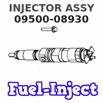
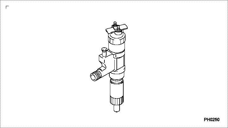
Information injector assy
Rating:
Compare Prices: .
As an associate, we earn commssions on qualifying purchases through the links below

4PCS Fuel injector 095000-8930 0950008930 Fits for Isuzu 4HK1 6HK1 Engine
SXCCGMGQ Part Name:Fuel Injector || Part Number:095000-8930 0950008930 || Application:Fits for Isuzu 4HK1 6HK1 Engine || · Easy installation: Standardized interface design, easy installation, no additional modification, users can easily complete replacement and maintenance. || · Trustworthy: This product through strict quality testing, to provide reliable product quality and after-sales service, so that you use no worries.
SXCCGMGQ Part Name:Fuel Injector || Part Number:095000-8930 0950008930 || Application:Fits for Isuzu 4HK1 6HK1 Engine || · Easy installation: Standardized interface design, easy installation, no additional modification, users can easily complete replacement and maintenance. || · Trustworthy: This product through strict quality testing, to provide reliable product quality and after-sales service, so that you use no worries.

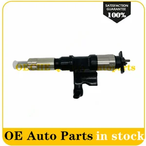
095000-8933 Common Rail Injector Nozzle 095000-8930 Fuel Inyector 8-98160061-3 8981600613 Compatible for Isuzu N-Series 4HK1 5.2L
FKFGBB Compatible for 095000-8933 Common Rail Injector Nozzle 095000-8930 Fuel Inyector 8-98160061-3 8981600613 || Precision manufacturing, improve fuel atomization efficiency. || Efficient adjustment of fuel injection volume and time to reduce fuel consumption. || Changing the injector can optimize fuel supply, improve acceleration performance and shorten acceleration time. || Check and maintain the injector regularly, replace parts, save fuel costs, improve efficiency, and extend engine life.
FKFGBB Compatible for 095000-8933 Common Rail Injector Nozzle 095000-8930 Fuel Inyector 8-98160061-3 8981600613 || Precision manufacturing, improve fuel atomization efficiency. || Efficient adjustment of fuel injection volume and time to reduce fuel consumption. || Changing the injector can optimize fuel supply, improve acceleration performance and shorten acceleration time. || Check and maintain the injector regularly, replace parts, save fuel costs, improve efficiency, and extend engine life.

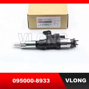
shsiyayh 6X Fuel Injector 095000-8931 095000-8930 for Isuzu 6HK1 4HK1 Diesel Engine
shsiyayh Part Name:Fuel Injector || Part Number:095000-8931 095000-8930 || APPlication: for Isuzu 6HK1 4HK1 Diesel Engine || 1.Please tell us of your engine model or a view of nameplate when order this item to lower the error rate.Thanks. || 2.There are no instructions included in this kit.it is recommended to install professionally.
shsiyayh Part Name:Fuel Injector || Part Number:095000-8931 095000-8930 || APPlication: for Isuzu 6HK1 4HK1 Diesel Engine || 1.Please tell us of your engine model or a view of nameplate when order this item to lower the error rate.Thanks. || 2.There are no instructions included in this kit.it is recommended to install professionally.
You can express buy:
USD 128
19-05-2025
19-05-2025
New 8-98160061-3 8981600613 095000-8933 Common Rail Injector Nozzle 095000-8930 Fuel Inyector for Isuzu N-Series 4HK1 5.2L
USD 22.01
16-05-2025
16-05-2025
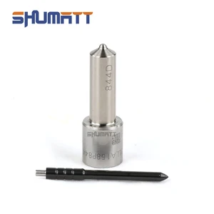
China Made New DLLA158P844 093400-8440 Fuel Injector Nozzle For 095000-6360 095000-5340 095000-8930 8-98160061-0 Injector
USD 105
13-05-2025
13-05-2025
095000-8933 Common Rail Injector Nozzle 095000-8930 Fuel Inyector 8-98160061-3 8981600613 For Isuzu N-Series 4HK1 5.2L
Images:
USD 231.31

[13-May-2025]
USD 118.05

[13-May-2025]
USD 80

[13-May-2025]
USD 88.71

[19-May-2025]
Components :
| 001. | INJECTOR ASSY | 09500-08930 |
Scheme ###:
| 000. | [01] | 09500-08930 | INJECTOR ASSY | 8-98160061-0 |
| 000. | [01] | 09500-08931 | INJECTOR ASSY | 8-98160061-1 |
| 000. | [01] | 09500-08932 | INJECTOR ASSY | 8-98160061-2 |
Include in #3:
09500-08930
as INJECTOR ASSY
Cross reference number
| Part num | Firm num | Firm | Name |
| 09500-08930 | 8-98160061 | INJECTOR ASSY | |
| 8-98160061-2 | ISUZU | INJECTOR ASSY | |
| 8-98160061-1 | ISUZU | INJECTOR ASSY | |
| 8-98160061-0 | ISUZU | INJECTOR ASSY |
Information:
Start By:a. remove oil pumpb. remove oil pan plate
Keep all parts clean from contaminants. Contaminants put into the system may cause rapid wear and shortened component life.
1. Remove No. 1, 3, 5 and 7 main bearing caps (1). Remove the lower halves of the main bearings from the main bearing caps.
If the crankshaft is turned in the wrong direction, the tab on the bearing will be pushed between the crankshaft and the bearing area in the cylinder block. This can result in damage to the cylinder block and/or the crankshaft.
2. Install tool (A) in the hole in the crankshaft journal, and turn the crankshaft to remove the upper halves of main bearings (2).3. Remove crankshaft thrust bearings (3). Install the main bearings dry when the clearance checks are made. Put clean engine oil on the main bearings for final assembly.
Make sure the upper and lower halves of the main bearings are installed so the bearing tabs fit into the notch in the cylinder block and the main bearing caps.
4. Use tool (A), and install new upper halves of main bearings (2) in the cylinder block. Install new lower halves of main bearings (2) in main bearing caps (1).
When the bearing clearance is checked and the engine is in an upright position (vertical position with cylinder head on top), the crankshaft will have to be lifted up and held against the upper halves of the main bearings to get a correct measurement with the Plastigage. The Plastigage will not hold the weight of the crankshaft and give a correct indication. If the engine is in a horizontal position, it is not necessary to hold the crankshaft up. Do not turn the crankshaft when the Plastigage is in position to check clearances.
For complete details concerning measuring bearing clearances, see Engine Bearings And Crankshafts, Form No. SEBD0531.5. Check the main bearing clearance with Plastigage (B) as follows:a. Put a piece of Plastigage (B) on the crankshaft journals as shown.
Make sure the part number on the main bearing cap is toward the front of the engine and the number on the main bearing cap is the same as the number on the cylinder block on the left side of each main bearing cap.
b. Put main bearing caps (1) in position in the engine. Put 2P2506 Thread Lubricant on the bolt threads and the face of the washers, and install the bolts. Tighten the bolts to a torque of 40 4 N m (30 3 lb ft).c. Put a mark on each bolt and main bearing cap; then tighten the bolts 90° more.d. Remove the main bearing caps, and measure the Plastigage to find the bearing clearance. The main bearing clearance for new bearings must be 0.076 to 0.165 mm (.0030 to .0065 in). Maximum permissible clearance with used bearings is 0.25 mm (.010 in). 6. Put clean oil on the thrust bearing, and install a new thrust bearing for the rear main bearing. Install the thrust bearing with the identification