Information injector assy
Rating:
Compare Prices: .
As an associate, we earn commssions on qualifying purchases through the links below


10# 095000-6350 095000-5921 095000-8650 095000-8220 095000-8290 095000-6340 095000-6581095000-7580
Generic
Generic
You can express buy:
USD 153
13-05-2025
13-05-2025
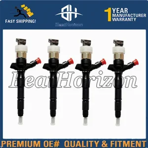
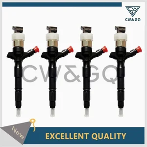
Common rail injector 095000-8290 for 23670-0L050, 23670-09330
USD 153.05
13-05-2025
13-05-2025
Common rail injector 095000-8290 for 23670-0L050, 23670-09330
USD 19.99
13-05-2025
13-05-2025
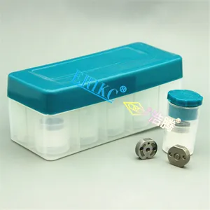
095000-8290 23670-0L050 Diesel Injector Control Valve Orifice Plate for Hilux 1KD-FTV 2KD-FTV 3.0L D-4D
Images:
USD 99.96

[13-May-2025]
USD 1.9

[13-May-2025]
USD 12

[13-May-2025]
USD 1.5

[13-May-2025]
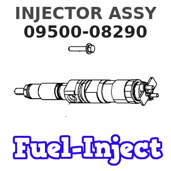
Components :
| 001. | INJECTOR ASSY | 09500-08290 |
| 002. | INJECTOR ASSY | 09500-08222 |
Scheme ###:
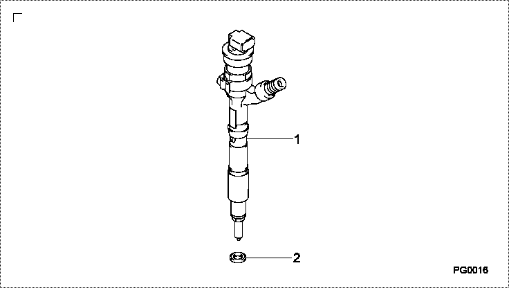
| 000. | [01] | 09500-08290 | INJECTOR ASSY | SM |
| 001. | [01] | 09500-08222 | INJECTOR ASSY | SM |
| 002. | [01] | 09313-30860 | GASKET | SM |
Include in #3:
09500-08290
as INJECTOR ASSY
Cross reference number
| Part num | Firm num | Firm | Name |
| 09500-08290 | SM | INJECTOR ASSY | |
| 23670-09330 | TOYOTA | INJECTOR ASSY | |
| SM | TOYOTA | INJECTOR ASSY |
Information:
1. Drain the cooling system. 2. Loosen hose clamps (1) and (3). Disconnect hoses (2) and (4). 3. Support pump (5) and remove four bolts (6). 4. Remove elbow (7) and the gasket. The following steps are to install the water pump.5. Install a new gasket and elbow (7).6. Put the water pump (5) and elbow (7) in position and install four bolts (6).7. Put hoses (2) and (4) in position on elbow (7) and tighten the clamps (1) and (3).8. Fill the cooling system to the correct level. See the Maintenance Manual.Disassemble And Assemble Water Pump
Start By:a. remove water pump
Keep all parts clean from contaminants. Contaminants put into the system may cause rapid wear and shortened component life.
1. Remove bolt (15) and the washer. Remove bearing (12) and gear (10) as a unit.2. Use tooling (A), (C) and a press, and remove bearing (12) from gear (10).3. Remove snap ring (8) with tool (B).4. Remove two bolts (1), the washers, cover (14) and gasket (2) from water pump housing (18).5. Loosen bolt (13) approximately 6.4 mm (.25 in). Hit the bolt with a soft hammer to loosen impeller (16).6. Remove bolt (13), washer (11), impeller (16), spring (3) and seal assembly (4).7. Remove bearing (7) and shaft (9) as a unit.8. Use tooling (A), (C) and a press to remove bearing (7).9. Remove ceramic seal (5) and seal (17).10. Use tool (C) to remove lip-type seal (6). The following steps are for assembly of the water pump.11. Install hydrodynamic seal (6) in water pump housing (18) with tool (C). The lip of the seal must be toward the bearings. Put clean engine oil on the lip of the seal.12. Install shaft (9) in bearing (7) with a press.13. Install shaft (9) and bearing (7) as a unit in water pump housing (18).14. Install snap ring (8) with tool (B).
Clean water only is permitted for use as a lubricant for assembly. Do not damage or put hands on the wear surface of the carbon ring or the ceramic ring. Install the ceramic ring with the smoothest face of the ring toward the carbon seal assembly.
15. Put ceramic ring (5) in position in seal (17). Use hand pressure and tool (D) to install the ceramic ring.16. Remove spring (3) from seal assembly (4). Use hand pressure and tool (D) to install the seal assembly. Push seal assembly (4) on shaft (9) until it makes light contact with ceramic ring (5).17. Install spring (3) on seal assembly (4). Put impeller (16) in position on shaft (9), and install washer (11) and bolt (13). Tighten bolt (13) to a torque of 38.0 1.5 N m (28 1 lb ft).18. Put gasket (2) and cover (14) in position and install the two washers and bolts (1).19. Install bearing (12) on gear (10) with a press.20. Position gear (10) and bearing (12) as a unit on shaft (9). Install the washer and bolt (15). Torque bolt (15) to 97 7