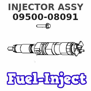
Information injector assy
Rating:
Compare Prices: .
As an associate, we earn commssions on qualifying purchases through the links below

XJMiao Compatible with Hino Fuel Injector 095000-8090 095000-8091 23670-E0390 Refurbished Parts with 3 Months
XJMiao Provides smooth engine operation. || Improved engine starting performance. || Reduce noise and vibration. || Fast response for improved acceleration performance. || Reduce engine maintenance costs.
XJMiao Provides smooth engine operation. || Improved engine starting performance. || Reduce noise and vibration. || Fast response for improved acceleration performance. || Reduce engine maintenance costs.

1PC Engine Fuel Injector 095000-8090 095000-8091 23670-E0390 for Hino for Kobelco for Denso with 3 Months
Generic Package Includes: 1 PC/Carton | -->
Generic Package Includes: 1 PC/Carton | -->

$207.69
25 Sep 2024
CN: CAR REFINE
Engine Fuel Injector Mechanism Fuel Injector Mechanism 095000-8091 095000-8091 23670-E0390 for Hino Kobelco Denso Truck Aftermarket Parts Months Warranty
Podafu Item Type: Fuel Injector || Part Code: 095000-8091 || Enhances the mixing process between fuel and air to promote complete combustion and longer service life. || Provides consistent fuel delivery to ensure smooth engine operation. || Extends the engine's peak performance, thereby improving the vehicle's dependability.
Podafu Item Type: Fuel Injector || Part Code: 095000-8091 || Enhances the mixing process between fuel and air to promote complete combustion and longer service life. || Provides consistent fuel delivery to ensure smooth engine operation. || Extends the engine's peak performance, thereby improving the vehicle's dependability.
You can express buy:

USD 8.99
10-11-2022
10-11-2022

USD 8.99
10-11-2022
10-11-2022

USD 8.99
10-11-2022
10-11-2022
Images:
USD 8.99

[10-Nov-2022]
USD 10.6

[10-Nov-2022]
USD 9.6

[22-Apr-2019]
USD 8.99

[24-Jun-2019]
Components :
| 001. | INJECTOR ASSY | 09500-08091 |
| 001. | INJECTOR ASSY | 09500-08091 |
| 001. | INJECTOR ASSY | 09500-08091 |
Scheme ###:

| 000. | [01] | 09500-08090 | INJECTOR ASSY | 23670-E0390 |
| 000. | [01] | 09500-08091 | INJECTOR ASSY | 23670-E0391 |
| 000. | [01] | 09500-08092 | INJECTOR ASSY | 23670-E0392 |
Include in #3:
09500-08091
as INJECTOR ASSY
Cross reference number
| Part num | Firm num | Firm | Name |
| 09500-08091 | 23670-E039 | INJECTOR ASSY |
Information:
Start By:a. disassemble governorb. remove fuel injection pumps
Keep all parts clean from contaminants. Contaminants put into the system may cause rapid wear and shortened component life.
1. Remove cover (1) and gasket. 2. Remove rack (2).
If the original lifters are to be installed in the fuel injection pump housing, put identification marks on them as to their location in the housing.
3. Remove lifters (3). 4. Put the fuel injection pump housing on end on blocks. Use tool (A) to remove snap ring (4). 5. Use a soft hammer to push the camshaft toward the governor end of the fuel injection pump housing to loosen washer (5). Remove washer (5). 6. Remove camshaft (6). 7. Remove bearings (7) from the drive end of the fuel injection pump housing. 8. Remove bearings (8) from the governor end of the fuel injection pump housing.Assemble Fuel Injection Pump Housing
Be sure all oil passages are clear, and put clean oil on all parts before assembly. 1. Use tooling (B) to install bearing (10) in the governor end of the fuel injection pump housing with junction (joint) (11) toward the top of the fuel injection pump housing. Install the bearing so it is 0.25 0.20 mm (0.10 0.008 in) below the surface of the housing.2. Use tooling (B) to install bearing (9) in the governor end of the fuel injection pump housing so it is 7.16 0.13 mm (0.282 0.005 in) below the surface of the housing. 3. Use tooling (B) to install bearing (12) in the drive end of the fuel injection pump housing with the junction (joint) in the bearing toward the top of the fuel injection pump housing. Install the bearing so it is 1.00 0.25 mm (9.039 0.010 in) below the surface of the housing. 4. Install plate (13) of tooling (C) on the drive end of the fuel injection pump housing to install the bearing for the rack. Use clean grease to hold the new rack bearing on driver (14) of tooling (C). Install the driver and bearing in plate (13) with the groove in the driver in alignment with the pin in the plate and use a hammer to push the bearing into position. The bearing will be installed to the correct depth when the shoulder of the driver is against plate (13).5. Remove tooling (C) from the fuel injection pump housing. The rack bearing must be installed so it is 0.25 0.25 mm (0.010 0.010 in) below the surface of the housing. 6. Install camshaft (6).7. Put the fuel injection pump housing on end, and place a block under the camshaft. 8. Put washer (5) over the end of the camshaft and use tooling (B) and a spacer (15) that has an inside diameter of 38.1 mm (1.5 in) and a length of 31.75 mm (1.25 in) to push the washer against its seat on the camshaft. Camshaft must have 0.285 0.235 mm (0.0112 0.0093 in) end play