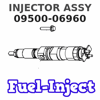
Information injector assy
Rating:
Compare Prices: .
As an associate, we earn commssions on qualifying purchases through the links below

$293.05
26 Oct 2024
KR: Adabus
095000-6960 095000-696# 095000-730# 095000-766# 095000-767# Diesel Injector Assembe 095000-6961 Fuel Injection 23670 0R030
Generic
Generic

$637.59
23 Apr 2024
0.1102[0.05] pounds
CN: linghupeng
IBLJNWZC Diesel Fuel Injector Assy 095000-7670, 095000-6410, 095000-6960, 095000-7300, 095000-7310, 095000-7660
IBLJNWZC High stability, optimized engine || High temperature resistance and long life || The nozzle :can be evenly sprayed into each cylinder to ensure uniformity and stability during combustion || The engine nozzle: can withstand the high-pressure injection system and the injection pressure to ensure stable fuel injection || The fuel nozzle :can precisely control the amount of oil injected each time to ensure that the engine's combustion efficiency and power output are at their best
IBLJNWZC High stability, optimized engine || High temperature resistance and long life || The nozzle :can be evenly sprayed into each cylinder to ensure uniformity and stability during combustion || The engine nozzle: can withstand the high-pressure injection system and the injection pressure to ensure stable fuel injection || The fuel nozzle :can precisely control the amount of oil injected each time to ensure that the engine's combustion efficiency and power output are at their best
Components :
| 001. | INJECTOR ASSY | 09500-06960 |
| 002. | INJECTOR ASSY | 09500-06411 |
Scheme ###:
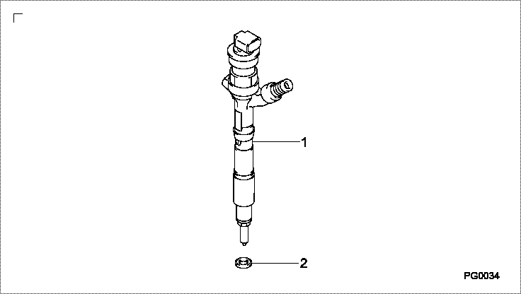
| 000. | [01] | 09500-06960 | INJECTOR ASSY | HU |
| 001. | [01] | 09500-06411 | INJECTOR ASSY | 23670-0R030-B |
| 002. | [01] | 09313-30810 | GASKET | 11176-26010 |
Include in #3:
09500-06960
as INJECTOR ASSY
Cross reference number
| Part num | Firm num | Firm | Name |
| 09500-06960 | HU | INJECTOR ASSY | |
| 23670-09180 | TOYOTA | INJECTOR ASSY | |
| HU | TOYOTA | INJECTOR ASSY |
Information:
Start By:a. disassemble governorb. remove fuel injection pumps
Keep all parts clean from contaminants. Contaminants put into the system may cause rapid wear and shortened component life.
1. Remove cover (1) and gasket. 2. Remove rack (2).
If the original lifters are to be installed in the fuel injection pump housing, put identification marks on them as to their location in the housing.
3. Remove lifters (3). 4. Put the fuel injection pump housing on end on blocks. Use tool (A) to remove snap ring (4). 5. Use a soft hammer to push the camshaft toward the governor end of the fuel injection pump housing to loosen washer (5). Remove washer (5). 6. Remove camshaft (6). 7. Remove bearings (7) from the drive end of the fuel injection pump housing. 8. Remove bearings (8) from the governor end of the fuel injection pump housing.Assemble Fuel Injection Pump Housing
Be sure all oil passages are clear, and put clean oil on all parts before assembly. 1. Use tooling (B) to install bearing (10) in the governor end of the fuel injection pump housing with junction (joint) (11) toward the top of the fuel injection pump housing. Install the bearing so it is 0.25 0.20 mm (0.10 0.008 in) below the surface of the housing.2. Use tooling (B) to install bearing (9) in the governor end of the fuel injection pump housing so it is 7.16 0.13 mm (0.282 0.005 in) below the surface of the housing. 3. Use tooling (B) to install bearing (12) in the drive end of the fuel injection pump housing with the junction (joint) in the bearing toward the top of the fuel injection pump housing. Install the bearing so it is 1.00 0.25 mm (9.039 0.010 in) below the surface of the housing. 4. Install plate (13) of tooling (C) on the drive end of the fuel injection pump housing to install the bearing for the rack. Use clean grease to hold the new rack bearing on driver (14) of tooling (C). Install the driver and bearing in plate (13) with the groove in the driver in alignment with the pin in the plate and use a hammer to push the bearing into position. The bearing will be installed to the correct depth when the shoulder of the driver is against plate (13).5. Remove tooling (C) from the fuel injection pump housing. The rack bearing must be installed so it is 0.25 0.25 mm (0.010 0.010 in) below the surface of the housing. 6. Install camshaft (6).7. Put the fuel injection pump housing on end, and place a block under the camshaft. 8. Put washer (5) over the end of the camshaft and use tooling (B) and a spacer (15) that has an inside diameter of 38.1 mm (1.5 in) and a length of 31.75 mm (1.25 in) to push the washer against its seat on the camshaft. Camshaft must have 0.285 0.235 mm (0.0112 0.0093 in) end play