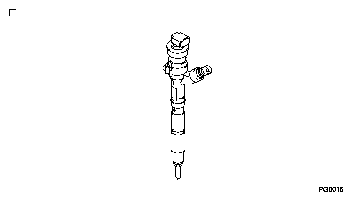
Information injector assy
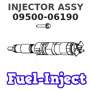
INJECTOR ASSY
AA
- SM095000-618# CANNOT BE SUPPLIED. SPARE PART NUMBER IS
- SM095000-593#.
Rating:
Compare Prices: .
As an associate, we earn commssions on qualifying purchases through the links below

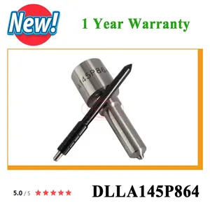
4PCS Fuel Injector Nozzle, Compatible With 095000-5930 095000-5880 095000-5660 095000-6190 095000-7390 095000-8740 095000-7760 DLLA145P864
CHENUXO 4PCS Fuel Injector Nozzle , Compatible With 095000-5930 095000-5880 095000-5660 095000-6190 095000-7390 095000-8740 095000-7760 DLLA145P864 || Controlling fuel volume: can maintain the optimal air-fuel ratio of the engine, improve fuel utilization, and reduce fuel waste. || Control time: Control the timing of fuel injection to ensure it enters the cylinder at the appropriate time. || Full combustion: More effectively utilizing the energy of fuel, improving power output, and reducing environmental pollution. || Reduce fuel consumption: It is beneficial for environmental protection and can also reduce fuel consumption, saving fuel costs.
CHENUXO 4PCS Fuel Injector Nozzle , Compatible With 095000-5930 095000-5880 095000-5660 095000-6190 095000-7390 095000-8740 095000-7760 DLLA145P864 || Controlling fuel volume: can maintain the optimal air-fuel ratio of the engine, improve fuel utilization, and reduce fuel waste. || Control time: Control the timing of fuel injection to ensure it enters the cylinder at the appropriate time. || Full combustion: More effectively utilizing the energy of fuel, improving power output, and reducing environmental pollution. || Reduce fuel consumption: It is beneficial for environmental protection and can also reduce fuel consumption, saving fuel costs.

4PCS DLLA145P864 Fuel Injector Nozzle Compatible For 095000-5930 095000-5880 095000-5660 095000-6190 095000-7390 095000-8740 095000-7760
YWQGNDJZ Fuel injection can be completed in a very short time. || The fuel injector can accurately control the fuel injection quantity. || Ensure that the engine can get timely fuel supply at various speeds and loads. || It has high heat resistance and corrosion resistance to ensure long-term stable operation. || 4PCS DLLA145P864 Fuel Injector Nozzle Compatible For 095000-5930 095000-5880 095000-5660 095000-6190 095000-7390 095000-8740 095000-7760
YWQGNDJZ Fuel injection can be completed in a very short time. || The fuel injector can accurately control the fuel injection quantity. || Ensure that the engine can get timely fuel supply at various speeds and loads. || It has high heat resistance and corrosion resistance to ensure long-term stable operation. || 4PCS DLLA145P864 Fuel Injector Nozzle Compatible For 095000-5930 095000-5880 095000-5660 095000-6190 095000-7390 095000-8740 095000-7760

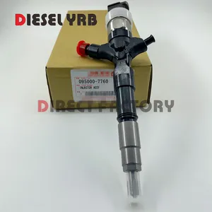
Diesel Fuel Injector Assembly 095000-6190 23670-30100 Compatible for HILUX Engine
QKGHMKL Diesel Fuel Injector Assembly 095000-6190 23670-30100 Compatible for HILUX Engine. || All applications provide precision flow rates and original spray patterns for optimal performance in all driving conditions. || Engineered for low consumption and emissions, particularly in the starting and warm-up phase, and outstanding warm-start performance. || The fuel injector balances fuel delivery, which can improve engine performance, effectively take car shaking off and enhance your driving experience. || The injectors is manufactured to the OE specification to provide, that promote smooth engine operation and balanced fuel delivery reducing overall fuel consumption.
QKGHMKL Diesel Fuel Injector Assembly 095000-6190 23670-30100 Compatible for HILUX Engine. || All applications provide precision flow rates and original spray patterns for optimal performance in all driving conditions. || Engineered for low consumption and emissions, particularly in the starting and warm-up phase, and outstanding warm-start performance. || The fuel injector balances fuel delivery, which can improve engine performance, effectively take car shaking off and enhance your driving experience. || The injectors is manufactured to the OE specification to provide, that promote smooth engine operation and balanced fuel delivery reducing overall fuel consumption.
You can express buy:
USD 872
14-06-2025
14-06-2025
4PCS Original new Injector 095000-7760, 095000-7761, 9709500-776, 23670-0L010, 23670-30300, 23670-39275, 095000-6190
USD 13.29
13-05-2025
13-05-2025
New DLLA145P864 Fuel Injector Nozzle for 095000-5930 095000-5880 095000-5660 095000-6190 095000-7390 095000-8740 095000-7760
USD 109
13-05-2025
13-05-2025
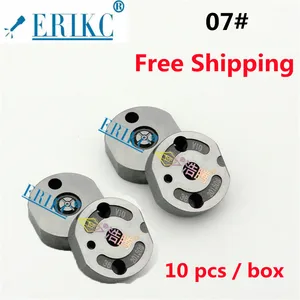
ERIKC Orifice Plate 07# 095000-5250 095000-6190 095000-7390 095000-7761 095000-5931 095000-6410 095000-7380 095000-7730
Images:
USD 42.99

[13-May-2025]
USD 19.99

[13-May-2025]
USD 61.74

[14-Jun-2025]
USD 110.8

[13-May-2025]
Components :
| 001. | INJECTOR ASSY | 09500-06190 |
Scheme ###:
| 000. | [01] | 09500-06190 | INJECTOR ASSY | SM |
Include in #3:
09500-06190
as INJECTOR ASSY
Cross reference number
| Part num | Firm num | Firm | Name |
| 09500-06190 | SM | INJECTOR ASSY | |
| 23670-30100 | TOYOTA | INJECTOR ASSY | |
| SM | TOYOTA | INJECTOR ASSY |
Information:
Keep all parts clean from contaminants. Contaminants put into the system may cause rapid wear and shortened component life.
1. Bend the lock tab and remove bolt (1).
The oil pump idler gear (3) can fall off the pump when the pump is removed. Injury can be the result. To prevent injury, always hold idler gear on the pump when the pump is removed.
2. Bend the two tabs on locks (4) on the left hand side of the engine. Remove the four bolts (2) and (5) and remove the oil pump and suction bell as a unit. Be sure the idler gear (3) is engaged with the crankshaft gear and tabs on locks (4) on bolts (5) are not next to the oil pan gasket surface when bolts (2) and (5) are tightened. Install in reverse order.End By:a. install oil pan
Perform Scheduled Oil Sampling on oil wetted compartments after performing service work to check for contaminants left in the system following repair. Contaminants put into the system may cause rapid wear and shortened component life.
Disassemble Oil Pump
Start By:a. remove oil pump
Keep all parts clean from contaminants. Contaminants put into the system may cause rapid wear and shortened component life.
1. Remove idler gear (2). Remove the bearing from the idler gear with tooling (B).2. Remove suction bell (1) and the bolt and the washer from the oil pump drive gear. 3. Remove the drive gear from the shaft with tooling (A).4. Remove the key from the pump shaft and bolts (3). 5. Remove body (8), two gears (7), the keys and spacer (4).6. Remove two shafts (5) and the gears.7. Remove bolts (6), the cover and the pressure relief valve. 8. Remove the bearings from the oil pump body assembly and the scavenge pump body assembly with tooling (B).Assemble Oil Pump
1. Install the bearings in the scavenge pump body assembly with tooling (B) and a press as follows:a. Put bearings (9) in position on the inside of the scavenge pump body assembly with the chamfer on the bearing toward the outside of the pump body. Install the bearing until it is 1.52 mm (.060 in) below the inside machined surface of the scavenge pump body assembly. Make sure the joints in the bearings are at an angle of 30° 15° from the center line through the bores in the scavenge pump body and toward the outlet passage of the pump. The outlet passage has a cavity between the bearing bores. 2. Install the bearings in oil pump body assembly with tooling (B) and a press as follows.a. Put bearings (10) in position on the inside of the oil pump body assembly with the chamfer on the bearings toward the outside of the pump body. Install the bearings until they are even with the outside of the pump at an angle of 30° 15° from the centerline through the bearing bores and toward the outlet passage of the pump. The outlet passage has a cavity between the bearing bores.3. Check