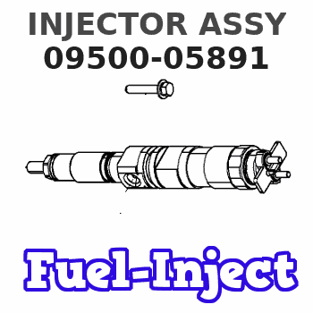
Information injector assy
Rating:
Compare Prices: .
As an associate, we earn commssions on qualifying purchases through the links below

$396.49
22 Nov 2024
VN: Laminee
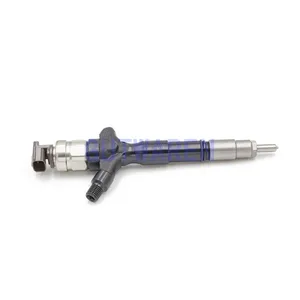
Higher Quality 095000-5891 Diesel fuel Injector 1KD-FFV diesel engine 23670-30080
Generic
Generic
Common Rail Injector 095000-5891 095000-5890 095000-5881 095000-5880 095000-5760 Diesel Nozzle - (Style: A, Color: 095000-5891)
Generic Color: 095000-5891
Generic Color: 095000-5891
$380.49
22 Nov 2024
VN: Laminee
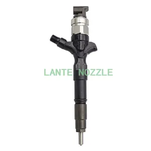
Common Rail Injector 095000-5891 095000-5890 095000-5881 095000-5880 095000-5760 Diesel Nozzle - (Style: A, Color: 095000-5890)
Generic Color: 095000-5890
Generic Color: 095000-5890
You can express buy:
USD 128
25-06-2025
25-06-2025
New Injector 095000-5740 095000-5890 095000-5891 095000-6870 Common Rail Nozzle Assembly Injection China Made
USD 148
23-06-2025
23-06-2025
Common Rail Injector 095000-5891 095000-5890 095000-5881 095000-5880 095000-5760 Diesel Nozzle

USD 19.99
13-05-2025
13-05-2025
ERIKC 07# Common Rail Diesel Fuel Engine Valves Suit for Inyectores C. Rail 095000-5890 095000-5891 23670-30210 23670-39295
Images:
USD 237.86

[19-May-2025]
USD 527.14

[14-Jun-2025]
USD 99.99

[27-Apr-2025]
USD 245

[10-Nov-2022]
Scheme ###:

| 000. | [01] | 09500-05890 | INJECTOR ASSY | 23670-39135 |
| 000. | [01] | 09500-05891 | INJECTOR ASSY | 23670-39136 |
| 001. | [01] | 09500-05741 | INJECTOR ASSY | 23670-30080 |
| 002. | [01] | 09313-30720 | GASKET | 11176-30010 |
| 002. | [01] | 09313-30830 | GASKET | 11176-30011 |
Include in #3:
09500-05891
as INJECTOR ASSY
Cross reference number
| Part num | Firm num | Firm | Name |
| 09500-05891 | 23670-3913 | INJECTOR ASSY |
Information:
Keep all parts clean from contaminants. Contaminants put into the system may cause rapid wear and shortened component life.
1. Turn the crankshaft until the "C" mark on the crankshaft gear is in alignment with the "C" mark on the camshaft gear. To keep the engine timing correct during removal and installation of the camshaft, put a mark on the teeth of the fuel injection pump drive gear and idler gear at location (A). Put a mark on the teeth of the idler gear and camshaft gear at location (B). When installing the camshaft, the engine timing will be correct when the marks at locations (A) and (B) are in alignment and the "C" marks on the crankshaft and camshaft gears are in alignment.2. Remove the bolts, lock and washer (1) that hold the camshaft in position.
Do not cause damage to the lobes or bearings when the camshaft is removed.
3. Remove the camshaft and gear (2).4. If necessary, remove the bolts and gear. The following steps are for the installation of the camshaft.5. Put the camshaft drive gear in position on the end of the camshaft, and install the bolts that hold it. Tighten the bolts to a torque of 55 7 N m (41 5 lb ft).
Do not cause damage to the lobes or bearings when the camshaft is installed.
6. Put 2P2506 Thread Lubricant on the camshaft lobes only, and clean engine oil on the bearing journals. Install camshaft (3) aligning the "C" marks and the marks put on the gears during removal.7. Install washer (1), the lock and bolts.End By:a. install valve liftersb. install timing gear cover
Perform Scheduled Oil Sampling on oil wetted compartments after performing service work to check for contaminants left in the system following repair. Contaminants put into the system may cause rapid wear and shortened component life.