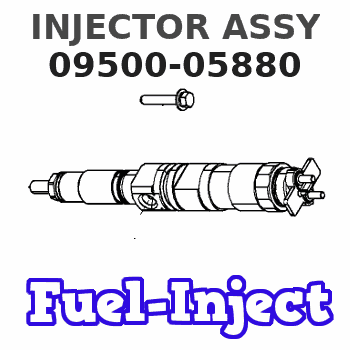
Information injector assy
Rating:
Compare Prices: .
As an associate, we earn commssions on qualifying purchases through the links below

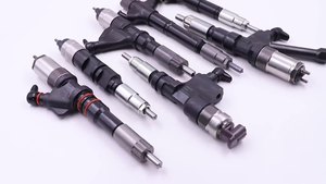
4PCS DLLA145P864 Fuel Injector Nozzle For 095000-5930 095000-5880 095000-5660 095000-6190 095000-7390 095000-8740 095000-7760
FICMVLQC By adopting high-precision processing techniques, the dimensions of each component of the fuel injector are ensured to be precise, guaranteeing the accuracy and stability of fuel injection. || It can fully atomize diesel fuel, enabling better mixture of fuel and air, and promoting efficient combustion. || It is usually manufactured with high-strength, high-temperature-resistant and corrosion-resistant alloy materials to ensure long-term stable operation. || It has excellent sealing performance, preventing fuel leakage and ensuring stable fuel injection pressure. || 4PCS DLLA145P864 Fuel Injector Nozzle For 095000-5930 095000-5880 095000-5660 095000-6190 095000-7390 095000-8740 095000-7760
FICMVLQC By adopting high-precision processing techniques, the dimensions of each component of the fuel injector are ensured to be precise, guaranteeing the accuracy and stability of fuel injection. || It can fully atomize diesel fuel, enabling better mixture of fuel and air, and promoting efficient combustion. || It is usually manufactured with high-strength, high-temperature-resistant and corrosion-resistant alloy materials to ensure long-term stable operation. || It has excellent sealing performance, preventing fuel leakage and ensuring stable fuel injection pressure. || 4PCS DLLA145P864 Fuel Injector Nozzle For 095000-5930 095000-5880 095000-5660 095000-6190 095000-7390 095000-8740 095000-7760

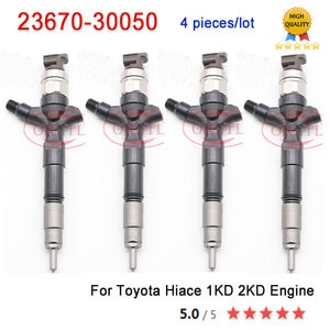
Parts# 23670-30050 095000-5880 095000-5881 095000-5660 23670-39095 Fuel Injector Assy 1piece/Pack DRAGOON-BRO
DRAGOON-BRO PARTS# 23670-30050 095000-5880 095000-5881 095000-5660 23670-39095 || Check your parts number before purchasing or send VIN to us,we will check the right parts number for you. || High performance and superior quality. || If you have any questions,please be free to contact us. || DRAGOON-BRO
DRAGOON-BRO PARTS# 23670-30050 095000-5880 095000-5881 095000-5660 23670-39095 || Check your parts number before purchasing or send VIN to us,we will check the right parts number for you. || High performance and superior quality. || If you have any questions,please be free to contact us. || DRAGOON-BRO

4PCS DLLA145P864 Fuel Injector Nozzle For 095000-5930 095000-5880 095000-5660 095000-6190 095000-7390 095000-8740 095000-7760
UCLMCNID Made of high-strength and corrosion-resistant alloy materials to extend the service life. || It can spray fuel in extremely fine particle form, mix it thoroughly with air, achieve efficient combustion, and improve fuel economy. || Adapting to different working conditions, precise fuel injection can be achieved whether idling, accelerating, or driving at high speeds. || High precision manufacturing, utilizing advanced processing techniques to ensure the dimensional accuracy and performance consistency of fuel injectors. || 4PCS DLLA145P864 Fuel Injector Nozzle For 095000-5930 095000-5880 095000-5660 095000-6190 095000-7390 095000-8740 095000-7760
UCLMCNID Made of high-strength and corrosion-resistant alloy materials to extend the service life. || It can spray fuel in extremely fine particle form, mix it thoroughly with air, achieve efficient combustion, and improve fuel economy. || Adapting to different working conditions, precise fuel injection can be achieved whether idling, accelerating, or driving at high speeds. || High precision manufacturing, utilizing advanced processing techniques to ensure the dimensional accuracy and performance consistency of fuel injectors. || 4PCS DLLA145P864 Fuel Injector Nozzle For 095000-5930 095000-5880 095000-5660 095000-6190 095000-7390 095000-8740 095000-7760
You can express buy:
USD 186.8
23-11-2022
23-11-2022
Common Rail Fuel Injector 23670-30050 095000-5880 095000-5881 fuel injector FOR Hilux VIGO 2KD/Hiace
USD 398.96
12-11-2023
12-11-2023
4 pieces/lot 0950005880 Common Rail Injector 23670 30050 Diesel Engine 1KD 2KD Fuel Injector 2367030050 23670-30050 12F54006

USD 203.28
02-09-2022
02-09-2022
FUEL Injector FOR Hilux VIGO 2KD/Hiace 2.5 2KD OEM:23670-30050 23670-39096 095000-5880 23670-39095
Images:
USD 203.28

[02-Sep-2022]
USD 42.99

[10-Nov-2022]
USD 42.99

[10-Nov-2022]
USD 129.99

[10-Nov-2022]
Components :
| 001. | INJECTOR ASSY | 09500-05880 |
| 001. | INJECTOR ASSY | 09500-05880 |
| 002. | INJECTOR ASSY | 09500-05661 |
Include in #3:

Cross reference number
| Part num | Firm num | Firm | Name |
| 09500-05880 | 23670-3909 | INJECTOR ASSY | |
| 23670-39096 | TOYOTA | INJECTOR ASSY | |
| 23670-39095 | TOYOTA | INJECTOR ASSY |
Information:
Start By:a. remove timing gear cover 1. Remove bolt (1) and washer that fastens the weight assembly (2).
Weight assembly must have support during removal to prevent damage to components.
2. Install tooling (A) and remove the weight assembly.Install Automatic Timing Advance Unit
1. Install washer and bolt (1). With the fuel pump housing cover removed, turn the fuel pump camshaft in the direction of engine rotation until tool (A) can be installed in the notch of the camshaft. 2. To time the fuel injection pump to the engine with the front timing cover removed, follow Steps 3 and 4. With the timing cover installed, see Steps 6 and 7. No. 1 piston at top center (TC) on the compression stroke is the starting point for all timing procedures. The engine is seen from the flywheel end when direction of crankshaft rotation is given.3. Turn the crankshaft counterclockwise until the "C" on the crankshaft and camshaft and camshaft gears are in alignment. 4. Remove the plug and install tool (B) in the flywheel housing.5. To find top center compression stroke for No. 1 piston, turn the flywheel clockwise (opposite of engine rotation) approximately 30°. This procedure is to remove all end play from timing gears.6. Turn the flywheel counterclockwise (direction of engine rotation) until tool (B) can be installed in the flywheel. The piston is at top center. If you go past the bolt hole you must start over again. To see if the No. 1 piston is on the compression stroke, remove the breather assembly from the valve cover and look at the valves of the No. 1 cylinder. The valves will be closed if No. 1 cylinder is on the compression stroke. You must be able to move the rocker arms up and down with your hand.7. If NO. 1 piston is not on the compression stroke, remove tooling (B) and turn the flywheel 360° counterclockwise. Install tooling (B). The No. 1 piston is now at top center on the compression stroke.8. With tooling (A) and (B) installed in position, install the timing advance weight assembly on the fuel pump camshaft. 9. Install tooling (C) on the weight assembly. While a constant torque on drive gear on 68 N m (50 lb ft) is held, tighten the bolt that fastens the weight assembly to fuel pump camshaft to a torque of 270 25 N m (200 18 lb ft).10. Remove tooling (A), (B) and (C).End By:a. install timing gear coverDisassemble And Assemble Automatic Timing Unit
Start By:a. remove automatic timing advance unit
Keep all parts clean from contaminants. Contaminants put into the system may cause rapid wear and shortened component life.
1. Remove two screws (1) and plate (2).
The weights are held on position with two springs for each weight under compression. Carefully remove weights and springs to prevent possible injury.
2. Remove springs (4) and (5), weight (3) and slide (6) from each side of assembly. 3. If necessary, remove gear (7). Remove seals (11) and (10). The following steps