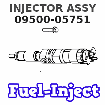
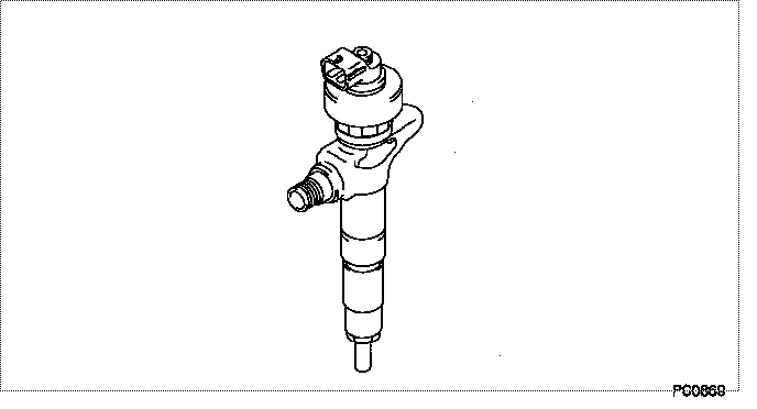
Information injector assy
Rating:
Compare Prices: .
As an associate, we earn commssions on qualifying purchases through the links below

1 Pc Fuel Injector 095000-5750 095000-5751 095000-5752 Compatible With Isuzu NLR85 Truck 4JJ1 Engine Excavator Part
TinYoo Durability: made of quality materials to ensure long-term durability || Convenient: simple installation, no need for professional tools, quick replacement of old parts || Advantages: Fuel injector accurately controls fuel, improving engine performance, fuel efficiency and emission reduction effect || Quality: After strict testing, the reliability and performance of the fuel injector are ensured || 1 Pc Fuel Injector 095000-5750 095000-5751 095000-5752 Compatible With Isuzu NLR85 Truck 4JJ1 Engine Excavator Part
TinYoo Durability: made of quality materials to ensure long-term durability || Convenient: simple installation, no need for professional tools, quick replacement of old parts || Advantages: Fuel injector accurately controls fuel, improving engine performance, fuel efficiency and emission reduction effect || Quality: After strict testing, the reliability and performance of the fuel injector are ensured || 1 Pc Fuel Injector 095000-5750 095000-5751 095000-5752 Compatible With Isuzu NLR85 Truck 4JJ1 Engine Excavator Part

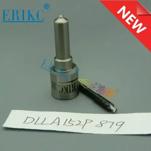
Common Rail Injector Nozzle Tips DLLA152P879 Diesel Fuel Injection Spray DLLA 152 P 879 for 095000-5751 095000-575#
Generic
Generic
You can express buy:
USD 109.99
19-05-2025
19-05-2025
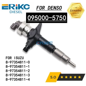
095000-5750 095000-5751 095000-5752 Common Rail Diesel Fuel Injector for Isuzu 8-97354811-0 8-97354811-1 8-97354811-2
USD 27.08
19-05-2025
19-05-2025
DLLA152P879 Common Rail Injector Nozzle DLLA 152 P 879, DLLA 152P 879 Injector Nozzle DLLA 152P879 for 095000-5751 095000-5750
USD 438.96
13-05-2025
13-05-2025
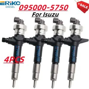
4PCS 095000-5750 Common Rail Diesel Fuel Injector 095000-5751 095000-5752 For DENSO 8-97354811-0 Isuzu D-MAX 4JJ1 8-97354811-1
Images:
USD 438.96

[13-May-2025]
USD 78.96

[13-May-2025]
USD 430.6

[13-May-2025]
USD 107.9

[13-May-2025]
Include in #3:
Cross reference number
| Part num | Firm num | Firm | Name |
| 09500-05751 | 8-97354811 | INJECTOR ASSY |
Information:
Keep all parts clean from contaminants. Contaminants put into the system may cause rapid wear and shortened component life.
1. Bend the lock tab and remove bolt (1).
The oil pump idler gear (3) can fall off the pump when the pump is removed. Injury can be the result. To prevent injury, always hold idler gear on the pump when the pump is removed.
2. Bend the two tabs on locks (4) on the left hand side of the engine. Remove the four bolts (2) and (5) and remove the oil pump and suction bell as a unit. Be sure the idler gear (3) is engaged with the crankshaft gear and tabs on locks (4) on bolts (5) are not next to the oil pan gasket surface when bolts (2) and (5) are tightened. Install in reverse order.End By:a. install oil pan
Perform Scheduled Oil Sampling on oil wetted compartments after performing service work to check for contaminants left in the system following repair. Contaminants put into the system may cause rapid wear and shortened component life.
Disassemble Oil Pump
Start By:a. remove oil pump
Keep all parts clean from contaminants. Contaminants put into the system may cause rapid wear and shortened component life.
1. Remove idler gear (2). Remove the bearing from the idler gear with tooling (B).2. Remove suction bell (1) and the bolt and the washer from the oil pump drive gear. 3. Remove the drive gear from the shaft with tooling (A).4. Remove the key from the pump shaft and bolts (3). 5. Remove body (8), two gears (7), the keys and spacer (4).6. Remove two shafts (5) and the gears.7. Remove bolts (6), the cover and the pressure relief valve. 8. Remove the bearings from the oil pump body assembly and the scavenge pump body assembly with tooling (B).Assemble Oil Pump
1. Install the bearings in the scavenge pump body assembly with tooling (B) and a press as follows:a. Put bearings (9) in position on the inside of the scavenge pump body assembly with the chamfer on the bearing toward the outside of the pump body. Install the bearing until it is 1.52 mm (.060 in) below the inside machined surface of the scavenge pump body assembly. Make sure the joints in the bearings are at an angle of 30° 15° from the center line through the bores in the scavenge pump body and toward the outlet passage of the pump. The outlet passage has a cavity between the bearing bores. 2. Install the bearings in oil pump body assembly with tooling (B) and a press as follows.a. Put bearings (10) in position on the inside of the oil pump body assembly with the chamfer on the bearings toward the outside of the pump body. Install the bearings until they are even with the outside of the pump at an angle of 30° 15° from the centerline through the bearing bores and toward the outlet passage of the pump. The outlet passage has a cavity between the bearing bores.3. Check