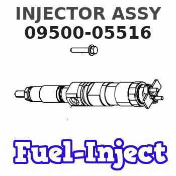
Information injector assy
Rating:
Compare Prices: .
As an associate, we earn commssions on qualifying purchases through the links below

095000-5516 8-97603415-7 Fuel Injector Fits Compatible With Isuzu N-Series 15.7L 6WF1 6WG1 6UZ1 Engine Hitachi ZX450 Excavator
GBQZKPVXN Fast response and stable power. || Stable performance and few failures. || Optimize combustion and reduce emissions. || Efficient and energy-saving, reducing fuel consumption. || The installation process is simple and convenient
GBQZKPVXN Fast response and stable power. || Stable performance and few failures. || Optimize combustion and reduce emissions. || Efficient and energy-saving, reducing fuel consumption. || The installation process is simple and convenient

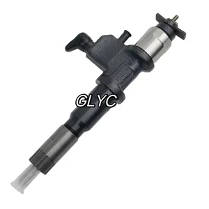
Fuel Injector 095000-5510 095000-5511 095000-5516 095000-5517 8-97603415-0 8-97603415-7 8-97603415-8,Compatible For SU-ZU GIGA
QEDADXD OEM NO. : 095000-5510, 095000-5511, 095000-5516, 095000-5517, 8-97603415-0, 8-97603415-7, 8-97603415-8 || Our fuel injectors deliver precise fuel injection to optimize engine performance and fuel efficiency. || Manufactured with OEM-compatible design, they ensure a perfect fit for seamless installation across various vehicle models. || Built with durable materials, they withstand extreme conditions for long-lasting use. || Each injector is rigorously tested for flow rate, spray pattern, and leakage to guarantee reliable performance.
QEDADXD OEM NO. : 095000-5510, 095000-5511, 095000-5516, 095000-5517, 8-97603415-0, 8-97603415-7, 8-97603415-8 || Our fuel injectors deliver precise fuel injection to optimize engine performance and fuel efficiency. || Manufactured with OEM-compatible design, they ensure a perfect fit for seamless installation across various vehicle models. || Built with durable materials, they withstand extreme conditions for long-lasting use. || Each injector is rigorously tested for flow rate, spray pattern, and leakage to guarantee reliable performance.

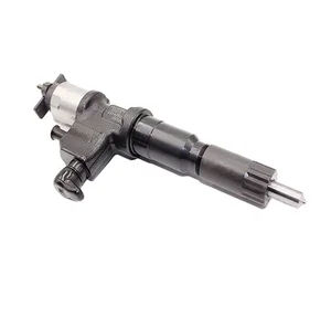
1X 0950005516 095000-5516 Fuel Injector Compatible with Isuzu 6WF1 6WG1 6UZ1 Engine N-Series 4HK1 5.2L Engine
Yuubryczny 🚕Part Name:Fuel Injector || 🚕Part Number: 0950005516 095000-5516 || 🚕Application:Compatible with Isuzu 6WF1 6WG1 6UZ1 Engine N-Series 4HK1 5.2L Engine || 🚕Precise matching is the first step towards safe driving! To ensure that the accessories fit perfectly with your beloved car, please make sure to check the product details page before placing an order or contact us privately. Your meticulousness is the best guarantee for driving safety! || 🚕"Thank you for your trust and support! If you have any questions regarding the products, please feel free to contact us at any time. We will do our best to solve them for you. Wish you a pleasant experience!"
Yuubryczny 🚕Part Name:Fuel Injector || 🚕Part Number: 0950005516 095000-5516 || 🚕Application:Compatible with Isuzu 6WF1 6WG1 6UZ1 Engine N-Series 4HK1 5.2L Engine || 🚕Precise matching is the first step towards safe driving! To ensure that the accessories fit perfectly with your beloved car, please make sure to check the product details page before placing an order or contact us privately. Your meticulousness is the best guarantee for driving safety! || 🚕"Thank you for your trust and support! If you have any questions regarding the products, please feel free to contact us at any time. We will do our best to solve them for you. Wish you a pleasant experience!"
You can express buy:
USD 355.78
14-06-2025
14-06-2025
Original Fuel Injector Assembly 095000-5516 Fuel Injector 8-97603415-7 8-98284393-0 For ISUZU 6WG1
USD 248.85
31-05-2025
31-05-2025
Competitively engine diesel injector 095000-5516 0950005516 with more models
USD 99.99
19-05-2025
19-05-2025
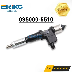
New Diesel Injector 095000-5510 Common Rail Nozzle Assy 095000-5513 095000-5516 for Isuzu N-Series 6WG1 15.7L 095000-5511
Images:
USD 59

[19-May-2025]
USD 155

[19-May-2025]
USD 19.99

[13-May-2025]
USD 14.2

[13-May-2025]
Include in #3:

Cross reference number
| Part num | Firm num | Firm | Name |
| 09500-05516 | 8-97603415 | INJECTOR ASSY |
Information:
1. Disconnect pressure line (3). Remove two bolts (2).2. Move fuel ratio control (1) up to disengage the fuel ratio control from the lever assembly in the governor. 3. Remove four O-ring seals (4) and screen assembly (5). The following steps are to install the fuel ratio control.4. Inspect, replace and install the four O-ring seals (4) and the screen assembly (5).5. Put the fuel ratio control (1) in position and engage the fuel ratio control with the lever assembly in the governor.6. Install the bolts that hold the fuel ratio control and connect pressure line (3) to the fuel ratio control (1). See Testing And Adjusting for Fuel Ratio Control Adjustment procedure.Disassemble And Assemble Fuel Ratio Control
Start By:a. remove fuel ratio control
Keep all parts clean from contaminants. Contaminants put into the system may cause rapid wear and shortened component life.
1. Remove the two bolts, and the fuel ratio control. Remove O-ring seal (1). 2. Put tooling (A) in a vise as shown so that the station being used is not over the vise jaw. Place the fuel ratio control over the pins in tooling (A). Remove cover (2) and the gasket.
There is spring force behind cover (3). Hold cover (3) in position, and slowly remove the bolts that hold it to release the spring force.
3. Remove cover (3). 4. Remove nut (5) and stop (6). 5. Remove spring (9), washer (7), and diaphragm (10) from retainer (8). Remove retainer (8) from housing (11). 6. Remove nut (16) from extension (15), and remove the extension from retainer (8). Remove valve (12), spring (13) and O-ring seal (14). 7. Remove spring (18), retainer (17) and spring (19). 8. Remove piston assembly (20). 9. Use tooling (B), and remove snap ring (21) and the wave washers from valve assembly (22). Remove piston assembly (23). Remove seal (24). 10. If necessary, remove stem (26) from valve (25).11. Clean and inspect all parts. Make a replacement of all parts that are worn or damaged. The following steps are to assemble the fuel ratio control.12. Assemble stem (26) to valve (25) using 9S3265 Retaining Compound.13. Put seal (24) on piston (23). Install piston (23) on valve assembly (22).14. Put two wave washers in position on valve (22). Use tooling (B) to install the snap ring on the valve assembly.15. Place housing (4) on tooling (A), and put tooling (C) into the bore of the housing. Lubricate tooling (C) with clean engine oil.16. Put a small amount of clean oil on the seal of the piston assembly, and push piston assembly (23) into position with a smooth swift motion.17. Place spring (9), retainer (17) and spring (19) in position in housing (4).18. Put O-ring seal (14) on extension (15). Put spring (13) and valve (12) in position on the extension.19. Lubricate O-ring seal (14) with clean engine oil. Install extension (15) in retainer (8). Install nut (16).20. Put diaphragm (10), washer (7) and spring (9) in position on retainer (8). Install retainer (8).21.