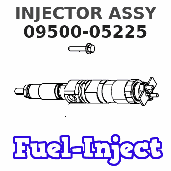
Information injector assy
Rating:
Compare Prices: .
As an associate, we earn commssions on qualifying purchases through the links below

1 Pcs Fuel Injector 095000-5224 095000-5225 095000-5226 23670-E0341 Compatible With HINO P13C E13C Engine Parts
TinYoo Durability: made of quality materials to ensure long-term durability || Convenient: simple installation, no need for professional tools, quick replacement of old parts || Advantages: Fuel injector accurately controls fuel, improving engine performance, fuel efficiency and emission reduction effect || Quality: After strict testing, the reliability and performance of the fuel injector are ensured || 1 Pcs Fuel Injector 095000-5224 095000-5225 095000-5226 23670-E0341 Compatible With HINO P13C E13C Engine Parts
TinYoo Durability: made of quality materials to ensure long-term durability || Convenient: simple installation, no need for professional tools, quick replacement of old parts || Advantages: Fuel injector accurately controls fuel, improving engine performance, fuel efficiency and emission reduction effect || Quality: After strict testing, the reliability and performance of the fuel injector are ensured || 1 Pcs Fuel Injector 095000-5224 095000-5225 095000-5226 23670-E0341 Compatible With HINO P13C E13C Engine Parts

shsiyayh 1PCS Fuel Injector for Hino P13C/E13C Engine Hino 700 Series Truck 095000-5225 0950005225
shsiyayh Part Name:Fuel Injector || Part Number:095000-5225 0950005225 || APPlication: Compatible with Hino P13C/E13C Engine Hino 700 Series Truck || 1.Please tell us of your engine model or a view of nameplate when order this item to lower the error rate.Thanks. || 2.There are no instructions included in this kit.it is recommended to install professionally.
shsiyayh Part Name:Fuel Injector || Part Number:095000-5225 0950005225 || APPlication: Compatible with Hino P13C/E13C Engine Hino 700 Series Truck || 1.Please tell us of your engine model or a view of nameplate when order this item to lower the error rate.Thanks. || 2.There are no instructions included in this kit.it is recommended to install professionally.

Fuel Injector 095000-5223 095000-5224 095000-5225 095000-5226 23910-1240 23670-E0340 23670-E0341,Compatible For Hino TRUCKE13C Engines
QEDADXD Part Number:095000-5223/095000-5224/095000-5225/095000-5226/23910-1240/23670-E0340/23670-E0341 || Precise Fuel Delivery: Ensures accurate fuel injection for improved engine efficiency. || Enhanced Combustion: Optimizes combustion for better power output and lower emissions. || Durable Construction: Built to withstand the demands of heavy-duty diesel engines. || Fuel Efficiency: Helps reduce fuel consumption, lowering overall operating costs.
QEDADXD Part Number:095000-5223/095000-5224/095000-5225/095000-5226/23910-1240/23670-E0340/23670-E0341 || Precise Fuel Delivery: Ensures accurate fuel injection for improved engine efficiency. || Enhanced Combustion: Optimizes combustion for better power output and lower emissions. || Durable Construction: Built to withstand the demands of heavy-duty diesel engines. || Fuel Efficiency: Helps reduce fuel consumption, lowering overall operating costs.
You can express buy:
USD 42.99
14-06-2025
14-06-2025
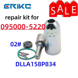
ERIKC 095000-5226 Diesel Injector Repair Kits DLLA158P834 Valve For HINO/FIAT 095000-5220 095000-5223 095000-5224 095000-5225
USD 1080
14-06-2025
14-06-2025
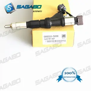
4PCS Original Diesel Engine iInjector 095000-5225, 095000-5221, 095000-5226, 23670-E0340, 23670-E0341
USD 236.01
19-05-2025
19-05-2025
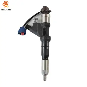
Fuel Injector 095000-5224 095000-5225 095000-5226 23670-E0341 For Hino P13C E13C 12.9L Engine 700 Series Trucks Fuel Accessories
Images:
USD 40.99

[13-May-2025]
USD 59

[13-May-2025]
USD 19.99

[13-May-2025]
USD 285.16

[13-May-2025]
Components :
| 001. | INJECTOR ASSY | 09500-05225 |
| 001. | INJECTOR ASSY | 09500-05225 |
| 001. | INJECTOR ASSY | 09500-05225 |
Scheme ###:

| 000. | [01] | 09500-05223 | INJECTOR ASSY | 23910-1240 |
| 000. | [01] | 09500-05224 | INJECTOR ASSY | 23670-E0340 |
| 000. | [01] | 09500-05225 | INJECTOR ASSY | 23670-E0341 |
Include in #3:
09500-05225
as INJECTOR ASSY
Cross reference number
| Part num | Firm num | Firm | Name |
| 09500-05225 | 23670-E034 | INJECTOR ASSY |
Information:
START BY:a. remove timing gear cover
Do not disconnect the air line from the air compressor governor until the air pressure is zero.
1. Loosen the bleed valves, and release the air pressure in the air tank. 2. Disconnect the lines from air compressor (1), and remove the air compressor. 3. Remove sleeve (2) from air compressor drive gear (3). 4. Remove the nut and washer that holds the air compressor drive gear to the air compressor. Use tooling (A) to remove air compressor drive gear (3) from the air compressor. 5. Remove nuts (4) and plate (5). Remove gear assembly (6) from the shaft. 6. If damaged, remove bearing (7) from gear (6) with tooling (B) and a press. 7. Remove three nuts (8) and the washers from the adapter assembly studs. 8. Remove adapter assembly (9) from the timing gear plate. 9. Remove shaft (10), O-ring seal (11) and sleeve (12) from the adapter assembly.Install Air Compressor And Accessory Drive
1. Install sleeve (1) into adapter assembly (2). 2. Install shaft (3) and O-ring seal (4) on the adapter assembly. 3. Put adapter assembly (2) in position on the timing gear plate. Fasten it with the three nuts and washers. 4. Install the bearing in gear (5) with tooling (A) and a press. Install the bearing until it is 1.5 0.5 mm (.06 .02 in.) below the surface of the gear as shown. 5. Put gear assembly (5) in position on shaft (3). 6. Put plate (6) in position, and install three nuts (7) to hold it. 7. Put gear (8) in position on the air compressor shaft, and install the washer and nut (9). Tighten the nut to a torque of 200 25 N m (150 18 lb.in.). Tap the gear with a hammer and tighten nut (9) again to a torque of 200 25 N m (150 18 lb.ft.). 8. Install sleeve (10) on gear (8). 9. Put a gasket in position on air compressor (11), and install the air compressor on the timing cover plate.END BY:a. install timing gear cover