Information injector assy

Rating:
Compare Prices: .
As an associate, we earn commssions on qualifying purchases through the links below

1PC 095000-5214 0950005214 AIQFTGSNS
AIQFTGSNS
AIQFTGSNS

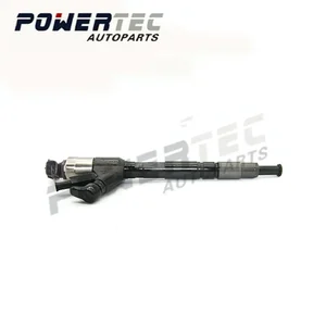
Fuel Injector 095000-5214 fits for Hino Engine P11C 6PCS
KoovDem Part Number: 095000-5214 || Part Name:Fuel Injectors || Quality Assurance: Each injector undergoes factory testing for flow rate, pressure retention and leak prevention || Compatibility Guarantee: Matches original equipment specifications for seamless performance integration || Please verify your required part number before ordering. You may also provide your vehicle details for our compatibility verification service.
KoovDem Part Number: 095000-5214 || Part Name:Fuel Injectors || Quality Assurance: Each injector undergoes factory testing for flow rate, pressure retention and leak prevention || Compatibility Guarantee: Matches original equipment specifications for seamless performance integration || Please verify your required part number before ordering. You may also provide your vehicle details for our compatibility verification service.
You can express buy:
USD 155.56
14-06-2025
14-06-2025
NEW Engine Diesel injection nozzle DLLA150P835 For Kobelco SK350-8/220-8 - Factory price 095000-5214 Common rail fuel injector
USD 12.13
28-05-2025
28-05-2025
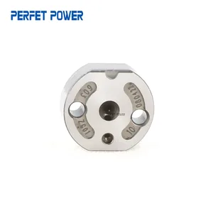
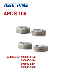
China Made New 10# Diesel Injector Control Valve Orifice Plate for 095000-5125 095000-5214 095000-5271 095000-5960 Injector
USD 44.65
28-05-2025
28-05-2025
4pcs 10# Orifice Valve for 095000-5125, 095000-5214, 095000-5271, 095000-5960 Common Rail Fuel Injector China Made New
Images:
USD 12.77

[13-May-2025]
USD 13.2
[13-May-2025]
USD 19.99

[13-May-2025]
USD 19.99
[13-May-2025]
Components :
| 001. | INJECTOR ASSY | 09500-05214 |
| 001. | INJECTOR ASSY | 09500-05214 |
| 001. | INJECTOR ASSY | 09500-05214 |
Scheme ###:

| 000. | [01] | 09500-05212 | INJECTOR ASSY | 23910-1252 |
| 000. | [01] | 09500-05213 | INJECTOR ASSY | 23670-E0350 |
| 000. | [01] | 09500-05214 | INJECTOR ASSY | 23670-E0351 |
Include in #3:
09500-05214
as INJECTOR ASSY
Cross reference number
| Part num | Firm num | Firm | Name |
| 09500-05214 | 23670-E035 | INJECTOR ASSY |
Information:
2. Remove the cylinder liners with tool (A) as shown. The Caterpillar pack pulling tools can be used to remove the cylinder liner, piston and connecting rod as a unit. For more detail, see Special Instruction, Form No. SEHS8554.Install Cylinder Liners
1. Clean the cylinder liners and the liner bores in the cylinder block. 2. Install cylinder liners (1) in the block without the O-ring seals or filler band. 3. Check the cylinder liner projection as follows:a. Install the 3/4"-16 NF bolts, 3 in. (76 mm) long and the 2F126 Washers of tooling (A) on the cylinder block next to each liner. Tighten the bolts evenly, in four steps: 14 N m (10 lb.ft.), 35 N m (26 lb.ft.), 70 N m (50 lb.ft.) and then turn to 95 N m (70 lb.ft.).b. Put the adapter plate and one plate of tooling (A) on top of the liner, and install the remainder of tooling (A). Be sure the bar is in position at the center of the liner. Tighten the bolts evenly, in four steps to a torque of 7 N m (5 lb.ft.), 20 N m (15 lb.ft.), 35 N m (25 lb.ft.) then to 70 N m (50 lb.ft.).c. Check to be sure the distance from the bottom edge of the bar to the top of the cylinder block is the same on both sides of the liner.d. Check the cylinder liner projection with tooling (B) at four locations around the liner. Special Instruction, Form No. SMHS7727, is included with the tool.e. Liner projection must be 0.03 to 0.15 mm (.001 to .006 in.). Measurements on the same liner must not be different by more than 0.05 mm (.002 in.). Average measurements between liners next to each other must not be different by more than 0.05 mm (.002 in.).The maximum difference in the average projection for all cylinder liners under one cylinder head must not be more than 0.10 mm (.004 in.). If the liner is turned in the bore it can make a difference in the liner projection. f. If the liner projection is not 0.03 to 0.15 mm (.001 to .006 in.), check the thickness of the following parts: spacer plate, spacer plate gasket and cylinder liner flange (3). The thickness of the spacer plate must be 8.59 0.03 mm (.338 .001 in.). The thickness of the spacer plate gasket must be 0.20 0.03 mm (.008 .001 in.). The thickness of the cylinder liner flange must be 8.890 0.020 mm (.3500 .0008). The cylinder liner projection can be changed by the correction of the counterbore in the block to a minimum depth of 0.76 mm (.030 in.) with an 8S3140 Cylinder Block Counterboring Tool. See Special Instruction, Form FM055228. A 5N93 Stainless Steel Insert is also available for use after the cylinder block has been counterbored. Special Instruction Form No. SMHS8222 has the correct installation procedure for the insert.4. Put a mark on the liner and block so the
1. Clean the cylinder liners and the liner bores in the cylinder block. 2. Install cylinder liners (1) in the block without the O-ring seals or filler band. 3. Check the cylinder liner projection as follows:a. Install the 3/4"-16 NF bolts, 3 in. (76 mm) long and the 2F126 Washers of tooling (A) on the cylinder block next to each liner. Tighten the bolts evenly, in four steps: 14 N m (10 lb.ft.), 35 N m (26 lb.ft.), 70 N m (50 lb.ft.) and then turn to 95 N m (70 lb.ft.).b. Put the adapter plate and one plate of tooling (A) on top of the liner, and install the remainder of tooling (A). Be sure the bar is in position at the center of the liner. Tighten the bolts evenly, in four steps to a torque of 7 N m (5 lb.ft.), 20 N m (15 lb.ft.), 35 N m (25 lb.ft.) then to 70 N m (50 lb.ft.).c. Check to be sure the distance from the bottom edge of the bar to the top of the cylinder block is the same on both sides of the liner.d. Check the cylinder liner projection with tooling (B) at four locations around the liner. Special Instruction, Form No. SMHS7727, is included with the tool.e. Liner projection must be 0.03 to 0.15 mm (.001 to .006 in.). Measurements on the same liner must not be different by more than 0.05 mm (.002 in.). Average measurements between liners next to each other must not be different by more than 0.05 mm (.002 in.).The maximum difference in the average projection for all cylinder liners under one cylinder head must not be more than 0.10 mm (.004 in.). If the liner is turned in the bore it can make a difference in the liner projection. f. If the liner projection is not 0.03 to 0.15 mm (.001 to .006 in.), check the thickness of the following parts: spacer plate, spacer plate gasket and cylinder liner flange (3). The thickness of the spacer plate must be 8.59 0.03 mm (.338 .001 in.). The thickness of the spacer plate gasket must be 0.20 0.03 mm (.008 .001 in.). The thickness of the cylinder liner flange must be 8.890 0.020 mm (.3500 .0008). The cylinder liner projection can be changed by the correction of the counterbore in the block to a minimum depth of 0.76 mm (.030 in.) with an 8S3140 Cylinder Block Counterboring Tool. See Special Instruction, Form FM055228. A 5N93 Stainless Steel Insert is also available for use after the cylinder block has been counterbored. Special Instruction Form No. SMHS8222 has the correct installation procedure for the insert.4. Put a mark on the liner and block so the