Information injector assy

Rating:
Compare Prices: .
As an associate, we earn commssions on qualifying purchases through the links below

095000-5215 095000-5210 095000-5211 Diesel Injection Nozzle Assy 095000-5212 For Denso 23670-E0351 Hino P11C Engine
Generic
Generic

$86.72
24 Nov 2024
KR: Adabus
Fuel Injectors Common Rail 095000-5215 Repair Kit for Hino Diesel Injection 095000-5212 095000-5213 095000-5214
Generic
Generic
$38.39
24 Nov 2024
KR: Adabus
23670-E0351 Common Rail Injector Nozzle Tips DLLA150P835 093400-8350 for Hino P11C 095000-5212 095000-5213 095000-5214
Generic
Generic
You can express buy:
USD 17.99
14-06-2025
14-06-2025
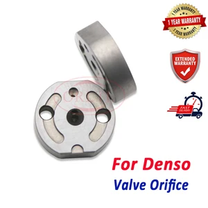
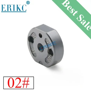
ORLTL 1465A041 Diesel Injector Valve Plate 02# Orifice Fuel for Mitsubishi 095000-5600 HINO 095000-5220 095000-5223 095000-5212
USD 19.99
14-06-2025
14-06-2025
23670-E0351 Injector Control Plate 02# forDenso Hino 700 095000-5215 095000-5210 095000-5211 095000-5212 095000-5220 095000-5221
USD 42.99
19-05-2025
19-05-2025
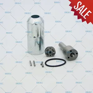
23910-1252 Erikc 5213 Injector Repair Kits DLLA150P835 093400-8350 5214 Hino P11C 095000-5212
Images:
USD 129.99

[13-May-2025]
USD 502.6

[13-May-2025]
USD 15

[13-May-2025]
USD 19.99

[13-May-2025]
Include in #3:

Cross reference number
| Part num | Firm num | Firm | Name |
| 09500-05212 | 23910-1252 | INJECTOR ASSY |
Information:
START BY:a. remove vibration damper and pulley
The crankshaft front seal and wear sleeve come as a set and must be installed as a set. If a replacement of the seal is to be made, a replacement of the wear sleeve must also be made.
1. Make at least three holes in seal (1) with a hammer and a sharp punch. 2. Use tool (A) to remove seal (1). 3. Install tool (C) in the seal bore.4. Install tool (B) between tool (C) and wear sleeve (2). Turn tool (B) until the tool makes a dent (crease) in wear sleeve (2). Do this in three or more places until the wear sleeve is loose.5. Remove tools (B) and (C), and remove wear sleeve (2) from the crankshaft.Install Crankshaft Front Seal And Wear Sleeve
The crankshaft seal and wear sleeve come as a set and must not be separated from each other at any time. Carefully read Special Instruction, Form No. SMHS8508, that is included with each seal and wear sleeve before any handling of the seal group is made.
1. Install the front crankshaft seal and wear sleeve with tooling (A). Use the procedure which follows:a. Clean and make a preparation of the wear sleeve inside diameter and crankshaft outside diameter with 6V1541 Quick Cure Primer. Make an application of 9S3265 Retaining Compound to the crankshaft outside diameter before the wear sleeve is installed on the crankshaft. Do not let any Quick Cure Primer or Retaining Compound get on the lip of the seal.b. Install locator (1) and bolts (3) on the crankshaft.c. Seal (6) and wear sleeve (2) must be installed dry.
Make sure the seal is installed with the part number and the arrows showing crankshaft rotation toward the outside.
The front and rear seals and wear sleeves have different spiral grooves in the seal. Because of this type of design, the front seal group for an engine is different from the rear seal group. If a seal group is installed on the wrong end of the engine, oil can actually be taken out of the engine instead of moving the oil back into the engine.
d. Put wear sleeve (2) and seal (6) as a unit in position on locator (1).e. Put installer (4) in position on locator (1).f. Put clean engine oil on the face of nut (5) and its contact area on installer (4). Install nut (5) on locator (1).g. Tighten nut (5) until the inside surface of installer (4) comes in contact with locator (1).h. Remove tooling (A) from the crankshaft seal and wear sleeve. Tooling (A) will install the seal and wear sleeve to the correct depth on the crankshaft.END BY:a. install vibration damper and pulley