Information injector assy

Rating:
Compare Prices: .
As an associate, we earn commssions on qualifying purchases through the links below

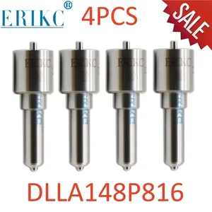
4 PCS 16600-AW400 DIESEL DLLA148P816 0934008160 FUEL Injector Nozzle DLLA 148 P 816 For Nissan 095000-5131 095000-5132 For
Generic
Generic

Auto Fuel Nozzle DLLA 148P816 (0934008160) Common Rail Diesel Spray DLLA 148P 816 for N1S SAN 095000-5132 095000-5133
Generic Is customized: yes || Material type: High-speed Steel || Item length: 5cm || Country of manufacture: UK || Type: DLLA148P816 Common rail diesel fuel Injector Nozzle
Generic Is customized: yes || Material type: High-speed Steel || Item length: 5cm || Country of manufacture: UK || Type: DLLA148P816 Common rail diesel fuel Injector Nozzle
You can express buy:
USD 84.41
19-05-2025
19-05-2025
4pcs DIESEL DLLA148P816 0934008160 FUEL Injector Nozzle DLLA 148 P 816 FOR 16600-AW400 Nissan 095000-5131 095000-5132
USD 19.99
13-05-2025
13-05-2025
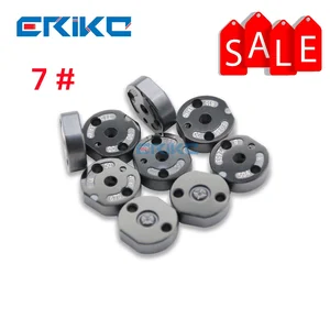
ERIKC 7# Valve Plate for DENSO 095000-513# 095000-5135 095000-5130 095000-5131 095000-5132 095000-5133 095000-5134,
USD 65.8
13-05-2025
13-05-2025
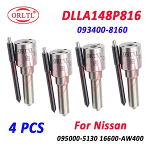
4 PCS 16600-AW400 DIESEL DLLA148P816 0934008160 FUEL Injector Nozzle DLLA 148 P 816 FOR Nissan 095000-5131 095000-5132 ORLTL
Images:
USD 19.99

[13-May-2025]
USD 17.9

[10-Nov-2022]
USD 40.99

[10-Nov-2022]
USD 40.99

[10-Nov-2022]
Include in #3:

Cross reference number
| Part num | Firm num | Firm | Name |
| 09500-05132 | 16600AW401 | INJECTOR ASSY |
Information:
1. Remove suction bell (3) and tubes, oil supply tube (2) and BrakeSaver oil supply tube (1) from the engine block and oil pump. 2. Remove three bolts (5) and oil pump (4) from the engine. The following steps are for installation of the oil pump.3. Put oil pump (4) in position on the engine. Make sure the oil pump gear is engaged with the crankshaft gear, and install three bolts (5) that hold the oil pump.4. Put clean engine oil on the O-ring seals on the oil tubes.5. Install suction bell (3) and tubes, oil supply tube (2) and the BrakeSaver oil supply tube (1).END BY:a. install oil pan (BrakeSaver)Disassemble Oil Pump (BrakeSaver)
START BY:a. remove oil pump (BrakeSaver) 1. Remove the bolt and washer that hold drive gear (1) on the shaft.2. Use tooling (A) to remove drive gear (1) from the shaft. Remove the key from the shaft. Put alignment marks on the pump bodies so they can be assembled in the correct position. 3. Remove retainer (3) for the bypass valve. Remove the spring and bypass valve.4. Remove bolts (4) that hold pump body (2) to the main pump body. Remove pump body (2).5. Use tooling (B) to remove the bearings from pump body (2). 6. Remove gears (7). Put identification marks on the gears so they can be assembled in the same position.7. Remove spacer (6) from main oil pump body (5). Use tooling (B) to remove the bearings from spacer (6).8. Remove the gears from main oil pump body (5). 9. Use tooling (B) to remove the bearings from the main oil pump body.Assemble Oil Pump (BrakeSaver)
1. Use tooling (A) to install bearings (2) until they are even with the outside surface of main oil pump body (1). Install bearings (2) so the joints in the bearings are 30° 15° from the center line of the bearing bores and toward the oil pump outlet passage as shown. 2. Use tooling (A) to install bearings (3) in the spacer. Install the bearings until they are in position an equal distance in from each side of the spacer. Install the bearings with the oil holes in the bearings in alignment with the oil holes in the spacer and the joints in the bearings in alignment with the cavity on the spacer as shown. 3. Put clean engine oil on all the gears and bearings before they are assembled in the oil pump. Install idler and drive gears (5) in the main oil pump body.4. Install spacer (4) on the gear shafts with the smaller cavity out and the oil holes in the spacer toward the pump outlet passage as shown. 5. Use tooling (A) to install bearings (6) in pump body (7) until they are 1.52 0.25 mm (.060 .010 in.) from the inside edge of the bearing bores. Install the bearings so the joints in the bearings are 30° 15° from the center line of the bearing bores and toward