Information injector assy

Rating:
Compare Prices: .
As an associate, we earn commssions on qualifying purchases through the links below

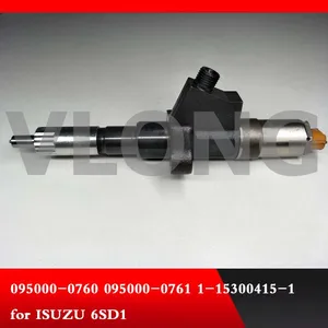
Fuel Injector 095000-0761 1-15300415-1 0950000761 For Isuzu Diesel Engine 6SD1 6SD1-T 6SD1T 9.8L 9.8D
oiasdfhjdg Product Name:Fuel Injector || Part Number:095000-0761 1-15300415-1 0950000761 || APPlication:For Isuzu Diesel Engine 6SD1 6SD1-T 6SD1T 9.8L 9.8D || 1.Please ensure to provide us with the correct, accurate, and detailed delivery address and contact information || 2.Please carefully compare the OE numbers before purchasing the product to match your original parts and avoid wasting your valuable time.
oiasdfhjdg Product Name:Fuel Injector || Part Number:095000-0761 1-15300415-1 0950000761 || APPlication:For Isuzu Diesel Engine 6SD1 6SD1-T 6SD1T 9.8L 9.8D || 1.Please ensure to provide us with the correct, accurate, and detailed delivery address and contact information || 2.Please carefully compare the OE numbers before purchasing the product to match your original parts and avoid wasting your valuable time.

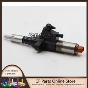
Seapple 6pcs Fuel Injector 095000-0761 1-15300415-1 Compatible with Isuzu Diesel Engine 6SD1 6SD1-T 6SD1T 9.8L 9.8D
Seapple Part Name: Fuel Injector || Part Number: 095000-0761 1-15300415-1 Note: Please check the fitment carefully before purchase. Or just tell us the part number you need. || Engine Model: 6SD1 || Applicable: Compatible with Isuzu Diesel Engine 6SD1 6SD1-T 6SD1T 9.8L 9.8D || Package included: 6pcs Fuel Injector 095000-0761 1-15300415-1
Seapple Part Name: Fuel Injector || Part Number: 095000-0761 1-15300415-1 Note: Please check the fitment carefully before purchase. Or just tell us the part number you need. || Engine Model: 6SD1 || Applicable: Compatible with Isuzu Diesel Engine 6SD1 6SD1-T 6SD1T 9.8L 9.8D || Package included: 6pcs Fuel Injector 095000-0761 1-15300415-1

You can express buy:
USD 325
19-05-2025
19-05-2025
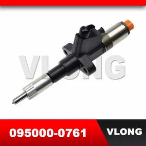
1PCS Genuine Diesel Common Rail Fuel Injectors Sprayer 095000-0760 095000-0761 For ISUZU 6SD1 Injector 1153004151 1-15300415-1
USD 394.9
13-05-2025
13-05-2025
095000-0761 Fuel Injector For Hitachi ISUZU 6SD1 Engine
USD 284.05
13-05-2025
13-05-2025
Fuel Injector Assembly For ISUZU 6SD1 Engine 1-15300415-0 1153004150 1-15300415-1 1153004151 0950000761 095000-0760 095000-0761
Images:
USD 420

[11-Oct-2022]
USD 430

[11-Oct-2022]
USD 340

[10-Nov-2022]
USD 84
[10-Nov-2022]
Components :
| 001. | INJECTOR ASSY | 09500-00761 |
Scheme ###:
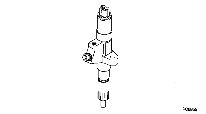
| 000. | [01] | 09500-00761 | INJECTOR ASSY | 1-15300415-1 |
Include in #3:
09500-00761
as INJECTOR ASSY
Cross reference number
| Part num | Firm num | Firm | Name |
| 09500-00761 | 1-15300415 | INJECTOR ASSY |
Information:
Do not overtighten the clamps.
(4) Diameter of shaft (new) ... 15.997 to 16.005 mm (.6298 to .6301 in) Bore in the bearing (new) ... 16.035 to 16.043 mm (.6313 to .6316 in)Maximum permissible clearance between bearing and shaft (worn) ... 0.05 mm (.002 in)(5) Maximum permissible gap of oil seal ring, measured in bore of housing ... 0.25 mm (.010 in)(6) Install the compressor wheel (at room temperature) as follows: a. See Compressor Wheel Clearance for the correct shim thickness to use.b. Put compressor wheel on the shaft.c. Put a small amount of clean engine oil on the threads.d. Tighten the nut to 14 to 17 N m (125 to 150 lb in).
Do not bend or add stress to the shaft when nut is loosened or tightened.
e. Remove nut from shaft and apply 6V1541 Quick Cure Primer on the threads of the shaft and nut followed by application of 9S3265 Retaining Compound.f. Tighten nut to 4 N m (30 lb in).g. Tighten nut more 90° rotation.(7) Shims. See Compressor Wheel Clearance for the correct shim thickness to use.(8) Thickness of each thrust ring ... 2.553 0.013 mm (.1005 .0005 in)(9) Bore in housing (new) ... 24.994 to 25.006 mm (.9840 to .9845 in) Outside diameter of the bearing (new) ... 24.882 to 24.892 mm (.9796 to .9800 in)Maximum permissible clearance between bearing and bore in housing (worn) ... 0.15 mm (.006 in)Torque for four nuts (put 5P3931 Anti-Seize Compound on threads) and bolts that hold turbocharger to exhaust manifold ... 55 5 N m (40 4 lb ft) Put clean engine oil in the oil inlet of the turbocharger after assembly or before installation to provide start up lubrication and/or storage protection.Compressor Wheel Clearance
a. Remove the compressor wheel from the cartridge group and place the wheel in the compressor housing. Center the wheel in the housing.b. Measure the distance from the compressor housing mounting face to the compressor wheel seating face. Measure four places at approximately 90° increments. This is dimension "A" (Fig. 1).c. Assemble the cartridge group complete except for the compressor wheel and shims. Hold the turbine wheel-shaft assembly toward the compressor end against the thrust bearing. Measure the distance from the bearing housing end face to the flinger sleeve. This is dimension "B" (Fig. 2).d. Measure the distance from the bearing housing end face to the compressor housing mounting face of the bearing housing. This is dimension "C" (Fig. 2).e. Shim thickness is C-B-A + 0.23 to 0.28 mm (C-B-A + .009 to .011 in). This is the thickness of the shims to be installed between the flinger sleeve and compressor wheel.f. Shims to be of uniform thickness and free of burrs or other imperfections. Shim thickness should total 0.13 to 0.41 mm (.005 to .016 in) and consist of one or two shims selected from those specified in Step g. All measurements to be taken with dry (no lubrication) turbocharger.g. Thickness of shims: 4W7362 Shim ... 0.076 mm (.003 in)4W7357