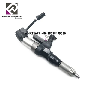
Information injector assy

Rating:
Compare Prices: .
As an associate, we earn commssions on qualifying purchases through the links below

IMIFAFTAbT New Fuel Injector 095000-0582 23910-1201 Compatible with Hino Diesel Engine SO5C
IMIFAFTAbT Product name: Fuel Injector || Warranty:1year || Compatible with Hino Diesel Engine SO5C || Part Number:095000-0582 23910-1201 || Important Note:1.Please double check that this product fits your car before purchasing check your part number,photo. 2.Since the effect of light is different between the display and the display, the actual color may be different from the color of the image.
IMIFAFTAbT Product name: Fuel Injector || Warranty:1year || Compatible with Hino Diesel Engine SO5C || Part Number:095000-0582 23910-1201 || Important Note:1.Please double check that this product fits your car before purchasing check your part number,photo. 2.Since the effect of light is different between the display and the display, the actual color may be different from the color of the image.

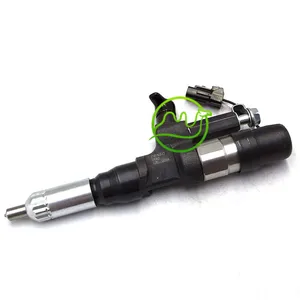
6Pcs Fuel Injector 095000-0582 0950000582 Compatible with Hino Diesel Engine S05C SO5
Starhycfa Product name:Fuel Injection || Part Number:095000-0582 0950000582 || APPlication:Compatible with Hino Diesel Engine S05C SO5 || 1.Please carefully compare the pictures or OE numbers to match your original parts before purchasing the product. || 2.Please make sure that the model number, part number and photo is the same as yours before order. To Avoid placing wrong orders and wasting your precious time.
Starhycfa Product name:Fuel Injection || Part Number:095000-0582 0950000582 || APPlication:Compatible with Hino Diesel Engine S05C SO5 || 1.Please carefully compare the pictures or OE numbers to match your original parts before purchasing the product. || 2.Please make sure that the model number, part number and photo is the same as yours before order. To Avoid placing wrong orders and wasting your precious time.

Fuel Injector 095000-0582 0950000582 Compatible with Hino Diesel Engine S05C SO5
Starhycfa Product name:Fuel Injection || Part Number:095000-0582 0950000582 || APPlication:Compatible with Hino Diesel Engine S05C SO5 || 1.Please carefully compare the pictures or OE numbers to match your original parts before purchasing the product. || 2.Please make sure that the model number, part number and photo is the same as yours before order. To Avoid placing wrong orders and wasting your precious time.
Starhycfa Product name:Fuel Injection || Part Number:095000-0582 0950000582 || APPlication:Compatible with Hino Diesel Engine S05C SO5 || 1.Please carefully compare the pictures or OE numbers to match your original parts before purchasing the product. || 2.Please make sure that the model number, part number and photo is the same as yours before order. To Avoid placing wrong orders and wasting your precious time.
You can express buy:
USD 359.09
14-06-2025
14-06-2025
For DENSO 095000-0582 Common Rail Fuel Injectors Injector & 23910-1201 Fuel Pump Parts

USD 293.89
19-05-2025
19-05-2025
Remanufactured Engine Diesel Fuel Injector 095000-0582 23910-1201 239101201
USD 392.24
14-06-2025
14-06-2025
Remanufactured Engine Diesel Fuel Injector 095000-0582 23910-1201 239101201
Images:
USD 153.56

[17-Jun-2025]
USD 510

[20-Oct-2022]
USD 220

[11-Nov-2022]
USD 90

[24-Jun-2019]
Components :
| 001. | INJECTOR ASSY | 09500-00582 |
| 001. | INJECTOR ASSY | 09500-00582 |
Scheme ###:
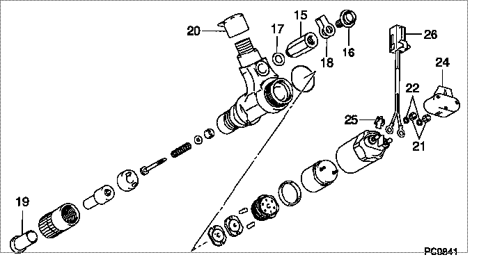
| 000. | [01] | 09500-00581 | INJECTOR ASSY | 23910-1201 |
| 000. | [01] | 09500-00582 | INJECTOR ASSY | S2391-01201 |
| 015. | [01] | 09507-10051 | CONNECTOR, FUEL OU | S2363-11090-A |
| 016. | [01] | 09507-40012 | SCREW, HOLLOW OUTL | S2283-51570-A |
| 017. | [01] | 09507-20020 | GASKET, OUTLET CON | S2287-72470-A |
| 018. | [01] | 09507-30010 | WASHER, OUTLET | 23661-1250B |
| 019. | [01] | 09003-40150 | PLUG | |
| 020. | [01] | 09001-40160 | CAP, VALVE HOLDER | |
| 021. | [02] | 94905-03370 | NUT, HEXAGON | S2282-52480-A |
| 022. | [02] | 94901-17590 | WASHER, STEEL PLAT | S2286-71860-A |
| 024. | [01] | 09508-90070 | COVER, INJECTOR | S2391-61220-A |
| 025. | [01] | 09508-70030 | GUIDE, HARNESS | S2288-58630-A |
| 026. | [01] | 09529-40100 | HARNESS, INJECTOR | S2391-51060-A |
Include in #3:
09500-00582
as INJECTOR ASSY
Cross reference number
| Part num | Firm num | Firm | Name |
| 09500-00582 | S2391-0120 | INJECTOR ASSY |
Information:
3. Remove bolts (1) and main bearing caps (2). Remove the lower halves of the main bearings from the caps.4. Install two of the bolts that hold the flywheel in place in the end of crankshaft. 5. Fasten a hoist and remove crankshaft (3) from the engine. The weight of the crankshaft is 54 kg (120 lb.).
Be careful not to cause damage to the crankshaft journals when the crankshaft is removed.
6. Remove the upper halves of the main bearings from the cylinder block.7. Install tooling (B) and remove the gear from the crankshaft. Install Crankshaft And Gear
1. Install the key for the crankshaft gear so it is even with the end of the crankshaft.2. Heat the crankshaft gear to a maximum temperature of 260°C (500°F). Install the gear on the crankshaft with the timing mark on the gear toward the pulley end of the crankshaft.3. Install the thrust bearing for the No. 4 main. Install the bearings dry when the clearance checks are made. Put clean engine oil on the bearings for final assembly.4. Install the upper main bearings (the bearings with oil hole) into the engine block.5. Install two of the bolts that hold the flywheel in place in the end of the crankshaft. Fasten a hoist and put the crankshaft in position in the block. Make sure the timing mark on the crankshaft gear is in alignment with the timing mark on the camshaft gear. For more detail about installation of main bearings see REMOVE AND INSTALL CRANKSHAFT MAIN BEARINGS.
When the bearing caps are installed, make sure the number on the side of the cap is next to and respective with the number on the engine block.
When the bearing clearance is checked and the engine is in a vertical position, the crankshaft will have to be lifted up with a force equal to the weight of the crankshaft and held against the upper halves of the main bearings to get a correct measurement with Plastigage. The Plastigage will not hold the weight of the crankshaft and give a correct indication. If the engine is in a horizontal position, such as on an engine stand, it is not necessary to hold the crankshaft up. Do not turn crankshaft when Plastigage is in position to check clearance. 6. Check the bearing clearance with Plastigage. Put the lower main bearings into the caps. Put the caps in position and install the bolts. Tighten the bolts in number sequence as follows: a) Tighten bolts 1 through 10 to a torque of 40 4 N m (30 3 lb.ft.).
Do not use an impact wrench to tigthen the nuts the additional 120 5°.
b) Put a mark on each bolt head and bearingcap. Tighten bolts 1 through 10 120 5° more.7. Remove the bearing caps and measure the thickness of the Plastigage. The main bearing clearance must be 0.076 to 0.168 mm (.0030 to .0066 in.). The maximum permissible clearance is 0.18 mm (.007 in.). 8. Put 2P2506 Thread