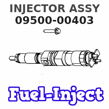
Information injector assy
Rating:
Compare Prices: .
As an associate, we earn commssions on qualifying purchases through the links below

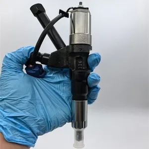
6Pcs New Common Rail Injector Compatible with HINO P11C Engine 095000-0402 095000-0403 095000-0404 23910-1163 23910-1164 S2391-01164
IMIFAFTAbT Product name: Fuel Injector || Warranty:1year || Compatible with HINO P11C Engine || Part Number:095000-0402 095000-0403 095000-0404 23910-1163 23910-1164 S2391-01164 || Important Note:1.Please double check that this product fits your car before purchasing check your part number,photo. 2.Since the effect of light is different between the display and the display, the actual color may be different from the color of the image.
IMIFAFTAbT Product name: Fuel Injector || Warranty:1year || Compatible with HINO P11C Engine || Part Number:095000-0402 095000-0403 095000-0404 23910-1163 23910-1164 S2391-01164 || Important Note:1.Please double check that this product fits your car before purchasing check your part number,photo. 2.Since the effect of light is different between the display and the display, the actual color may be different from the color of the image.

IMIFAFTAbT New Common Rail Injector 095000-0402 095000-0403 095000-0404 23910-1163 23910-1164 S2391-01164 Compatible with HINO P11C Engine
IMIFAFTAbT Product name: Fuel Injector || Warranty:1year || Compatible with HINO P11C Engine || Part Number:095000-0402 095000-0403 095000-0404 23910-1163 23910-1164 S2391-01164 || Important Note:1.Please double check that this product fits your car before purchasing check your part number,photo. 2.Since the effect of light is different between the display and the display, the actual color may be different from the color of the image.
IMIFAFTAbT Product name: Fuel Injector || Warranty:1year || Compatible with HINO P11C Engine || Part Number:095000-0402 095000-0403 095000-0404 23910-1163 23910-1164 S2391-01164 || Important Note:1.Please double check that this product fits your car before purchasing check your part number,photo. 2.Since the effect of light is different between the display and the display, the actual color may be different from the color of the image.

095000-0402 095000-0403 095000-0404 23910-1163 23910-1164 S2391-01164 Fuel Injector Fits for HINO P11C Engine (Pack of 6)
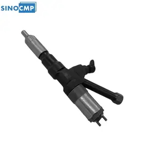
XYohykai ◆Part Name◆:Fuel Injector || ◆Part Number◆:095000-0402 095000-0403 095000-0404 23910-1163 23910-1164 S2391-01164 || ◆Application◆:Fits for HINO P11C Engine || ◆Notice◆-Application information provided is for reference only. Please confirm the part number and compare old parts before purchase. If you have any question,pls feel free to ask us. || ◆Worth Choice◆-This product has stable performance high reliability easy installation and fast response.
XYohykai ◆Part Name◆:Fuel Injector || ◆Part Number◆:095000-0402 095000-0403 095000-0404 23910-1163 23910-1164 S2391-01164 || ◆Application◆:Fits for HINO P11C Engine || ◆Notice◆-Application information provided is for reference only. Please confirm the part number and compare old parts before purchase. If you have any question,pls feel free to ask us. || ◆Worth Choice◆-This product has stable performance high reliability easy installation and fast response.
You can express buy:
USD 200
14-06-2025
14-06-2025
High Quality OEM Diesel Injector 095000-0401 095000-0402 095000-0403 For HINO Engine
USD 339.8
14-06-2025
14-06-2025
095000-0402 095000-0403 095000-0404 23910-1163 23910-1164 S2391-01164 SINOCMP 1PCS Fuel Injector For Hino Trucks P11C Engine
USD 49
13-05-2025
13-05-2025
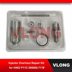
Diesel Injector Overhaul Kits For Hino P11C 700 Repair Parts Nozzle 095000-0400 095000-0403 095000-0404 23910-1163 23910-1164
Images:
USD 278.7

[14-Jun-2025]
USD 350.49

[14-Jun-2025]
USD 335.82

[07-May-2025]
USD 320

[28-Jun-2019]
Components :
| 001. | INJECTOR ASSY | 09500-00403 |
| 001. | INJECTOR ASSY | 09500-00403 |
| 001. | INJECTOR ASSY | 09500-00403 |
Scheme ###:

| 000. | [01] | 09500-00402 | INJECTOR ASSY | 23910-1163 |
| 000. | [01] | 09500-00403 | INJECTOR ASSY | 23910-1164 |
| 000. | [01] | 09500-00404 | INJECTOR ASSY | S2391-01164 |
Include in #3:
09500-00403
as INJECTOR ASSY
Cross reference number
| Part num | Firm num | Firm | Name |
| 09500-00403 | 23910-1164 | INJECTOR ASSY |
Information:
start by:a) remove turbocharger1. Make a mark on compressor housing (1), cartridge assembly (3) and turbine housing for correct installation. 2. Loosen clamp assemblies (2). Remove compressor housing (1) and cartridge assembly (3) from the turbine housing.3. Put the cartridge assembly in tooling (A).
When nut (5) is loosened, do not put a side force on the shaft.
4. Remove nut (5) and O-ring seal (6). 5. Put the cartridge assembly in a press. Remove the shaft assembly from compressor wheel (7) and cartridge (8). 6. Remove seal ring (10) and shroud (11) from shaft assembly (9).7. Use tooling (B) to remove snap ring (12).
Do not cause damage to insert (13) when it is removed.
8. Install screwdrivers as shown. Carefully lift insert (13) out of the cartridge assembly. 9. Remove sleeve (14) and O-ring seal (15) from the insert. 10. Remove two seal rings (16) from the sleeve.11. Remove deflector (17) from the cartridge assembly. 12. Remove ring (18). 13. Remove sleeve (19) from the cartridge assembly. Make an identification of the position of bearing (20) for assembly purposes.14. Remove bearing (20) from the cartridge assembly. 15. Remove ring (21). 16. Use tooling (C) to remove snap ring (23). Remove sleeve (22) and the lower snap ring. 17. Turn the cartridge housing over. Remove snap ring (26) with tooling (C).18. Remove bearing (25), sleeve (24) and the lower snap ring. Assemble Turbocharger (Schwitzer 4TF555)
Make sure all of the oil passages in the turbocharger cartridge housing are clean and free of dirt and foreign material. Put clean engine oil on all parts of the cartridge assembly. 1. Install snap ring (4) with tooling (A) in cartridge housing (1).2. Put sleeve (3) and bearing (2) in position. Install snap ring (5) with tooling (A).3. Turn the cartridge housing over. Install snap ring (8) with tooling (A). 4. Install sleeve (6) and snap ring (7).5. Put ring (10) in position in the cartridge housing. 6. Install bearing (9) with grooved side up. Make an alignment of the dowel in the housing with the hole on the right side of the notch.7. Put sleeve (12) in position. Install ring (11). 8. Put deflector (13) in position as shown. 9. Put two seal rings (15) in position on sleeve (14).10. Put O-ring seal (17) in position on insert (16). 11. Install sleeve (14) in insert (16).12. Install insert assembly (18) with the flange down in the cartridge housing. 13. Put O-ring seal (20) in position.14. Install snap ring (19) with tooling (B). 15. Put shaft assembly (22) in tooling (D). Put 6V2055 High Vacuum Grease in the groove for seal ring (23) at assembly to one half or more of the depth of the groove all the way around the groove. 16. Put seal ring (23) in position on the shaft assembly.17. Install shround (21) on the shaft assembly (22).18. Lightly oil the wheel face that will be under the nut. Put compressor wheel (24) in position.
Do not put a side force on the shaft