Information pump assy, injecti
Nozzle:
0935005170
Rating:
Components :
| 001. | PUMP ASSY, INJECTI | 09450-08760 |
Scheme ###:
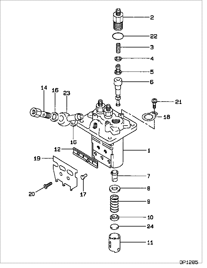
| 000. | [01] | 09450-08760 | PUMP ASSY, INJECTI | 131011130 |
| 001. | [01] | 09011-03680 | HOUSING SUB-ASSY, | 131296665 |
| 002. | [03] | 09013-00390 | HOLDER SUB-ASSY, D | 131196210 |
| 003. | [03] | 09013-60530 | SPRING, DELIVERY V | 131176430 |
| 004. | [03] | 09013-70130 | GASKET, DELIVERY V | 131186050 |
| 005. | [03] | 09014-01670 | VALVE SUB-ASSY, IN | 131156160 |
| 006. | [03] | 09015-06930 | ELEMENT SUB-ASSY, | |
| 007. | [03] | 09016-00140 | SLEEVE SUB-ASSY, C | 131296950 |
| 008. | [03] | 09016-30140 | SEAT, SPRING, UPR | 131296620 |
| 009. | [03] | 09016-40220 | SPRING, PUMP PLUNG | 131176440 |
| 010. | [03] | 09016-50170 | SEAT, SPRING, LWR | 131296621 |
| 011. | [03] | 09017-00220 | TAPPET SUB-ASSY,IN | 131256120 |
| 012. | [01] | 09021-00500 | RACK ASSY, CONTROL | 131296636 |
| 014. | [01] | 09024-50240 | SCREW, HOLLOW | 131236190 |
| 016. | [02] | 09025-10010 | WASHER, INJECTION | 131426180 |
| 017. | [03] | 09018-30090 | PIN, INJECTION PUM | 131296651 |
| 018. | [03] | 09023-00070 | PLATE SET, VALVE H | 131296662 |
| 019. | [01] | 09069-11020 | BRACKET, STOP WIRE | 131296650 |
| 020. | [02] | 94900-20500 | SCREW, COUNTERSUNK | 131136320 |
| 021. | [03] | 94900-75390 | SCREW, W/WASHER | 131136330 |
| 022. | [03] | 09013-90400 | O-RING | |
| 023. | [01] | 94918-10430 | NIPPLE, SWIVELING | 131246130 |
| 024. | [3C] | 09031-10440 | PLATE, TAPPET ADJU | 131296634 |
| 024. | [3C] | 09031-10430 | PLATE, TAPPET ADJU | 131296633 |
| 024. | [3C] | 09031-10420 | PLATE, TAPPET ADJU | 131296632 |
| 024. | [3C] | 09031-10410 | PLATE, TAPPET ADJU | 131296631 |
| 024. | [3C] | 09031-10400 | PLATE, TAPPET ADJU | 131296630 |
| 024. | [3C] | 09031-10390 | PLATE, TAPPET ADJU | 131296629 |
| 024. | [3C] | 09031-10380 | PLATE, TAPPET ADJU | 131296628 |
| 024. | [3C] | 09031-10370 | PLATE, TAPPET ADJU | 131296627 |
| 024. | [3C] | 09031-10360 | PLATE, TAPPET ADJU | 131296626 |
| 024. | [3C] | 09031-10350 | PLATE, TAPPET ADJU | 131296625 |
| 024. | [3C] | 09031-10340 | PLATE, TAPPET ADJU | 131296624 |
| 024. | [3C] | 09031-10330 | PLATE, TAPPET ADJU | 131296623 |
| 024. | [3C] | 09031-10320 | PLATE, TAPPET ADJU | 131296622 |
| 024. | [3C] | 09031-10450 | PLATE, TAPPET ADJU | 131296635 |
Include in #3:
09450-08760
as PUMP ASSY, INJECTI
Cross reference number
| Part num | Firm num | Firm | Name |
| 09450-08760 | 131011130 | PUMP ASSY, INJECTI | |
| 131011130 | ISHIKAWAJIMA | PUMP ASSY, INJECTI |
Information:
Automatic Start-Stop
An automatic start-stop system is used when an engine must start when a specific condition occurs with no one in attendance. The engine will start, increase speed, pick-up the load, operate the load until a second condition occurs, remove the load, cool and stop. The following conditions must exist for the engine to start unattended:Either the ambient (engine room) temperature must be at least 70°F (20°C); or, the engine jacket water temperature must be at least 90°F (32°C). One or two 3 kw jacket water heaters can maintain this temperature.Protection Devices
The Caterpillar generator mounted control panel is equipped with protection devices to protect the engine while cranking.Batteries
Lights or buttons may indicate if a fault has occurred in the battery charging system causing the battery to be either undercharged or overcharged.Overcranking
A timer allows the engine to crank either once for 30 seconds, or to crank through 5 ten-second cranking cycles (depending upon the device used) while unattended. If the engine does not start before the time elapsed, the fuel system will be shutoff and a light will indicate a starting failure. Engine Operation
Prealarm systems provide an audible and/or a visual indication for low oil pressure, high water temperature, low fuel supply or low jacket water temperature before the condition becomes critical. These alarms are self resetting when the condition is corrected. The engine may also be equipped with shutdown devices. If low oil pressure, high jacket water temperature or an engine overspeed condition occurs, the engine will be shutdown and a corresponding button or light will indicate the cause of the shutdown. These devices must be reset after repairs have been made and before starting. See the topic, EMERGENCY SHUTOFF DEVICES AND ALARMS.Generator set control panels should be equipped with an ammeter, a frequency meter and a voltmeter. Depending upon the type of operation, the panel may also be equipped with other meters and lights. Know these instruments and their normal readings. They will indicate how the generator set is performing.Shutting Down
A timer allows the transfer switch to transfer the load to another source and to continue engine running for up to 2 minutes for cooling purposes before stopping.Engine Exerciser
At preset times, the exerciser will start, run and stop the engine in order to ensure both proper lubrication of all engine parts and proper equipment operation if and when the standby unit is needed.Become familiar with all instructions included with the equipment.Woodward Governors
Woodward Governors are usually electrically operated from a control panel.Generator Set Control Panel
The generator set control panel is located on top of the generator and is equipped with the following controls and gauges:Panel lights (1) are controlled by an ON/OFF switch (7). An ammeter (2), frequency meter (3) and a voltmeter (4) show the output of the generator. Two gauges (5 and 6) show engine oil pressure and water temperature respectively. The ammeter selector switch (12) gives the operator a choice of which phase (T1, T2 or T3) of the generator output the ammeter (2) will