Information pump assy, injecti
Nozzle:
0935004540
Rating:
Components :
| 001. | PUMP ASSY, INJECTI | 09450-08540 |
Scheme ###:
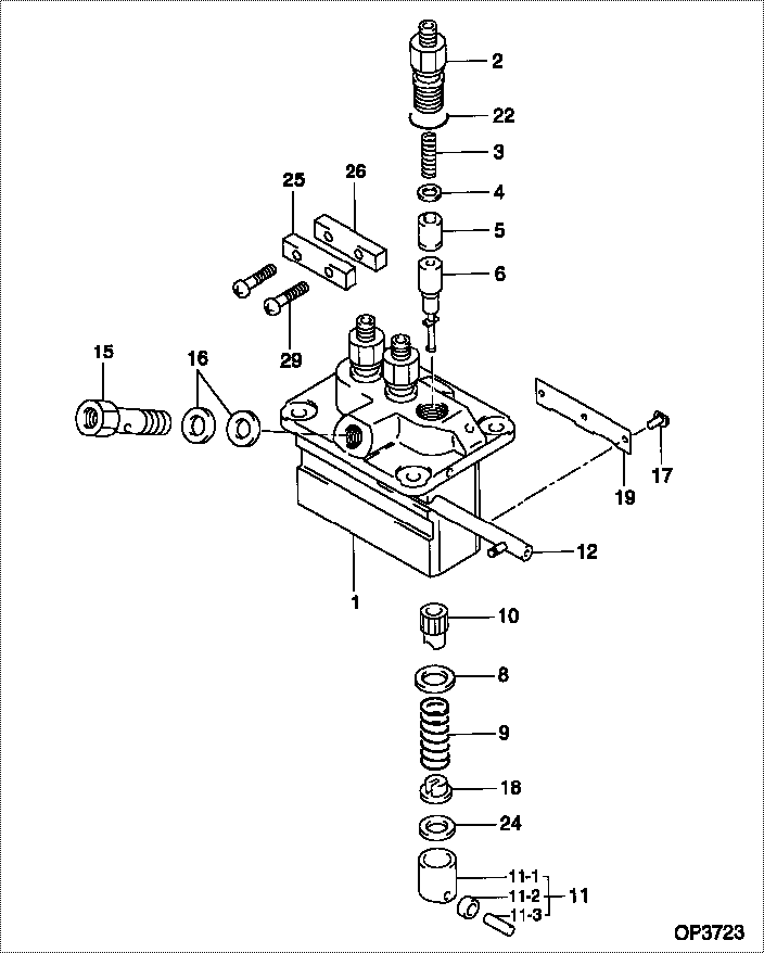
| 000. | [01] | 09450-08540 | PUMP ASSY, INJECTI | 1G711-51011 |
| 001. | [01] | 09011-12490 | HOUSING, PUMP | |
| 002. | [03] | 09013-00450 | HOLDER SUB-ASSY, D | 16415-51221 |
| 003. | [03] | 09013-60970 | SPRING, DELIVERY V | 16475-51231 |
| 004. | [03] | 09013-70130 | GASKET, DELIVERY V | 11420-51241 |
| 005. | [03] | 09014-02050 | VALVE SUB-ASSY, IN | 16475-51031 |
| 006. | [03] | 09015-06790 | ELEMENT SUB-ASSY, | |
| 008. | [03] | 09016-30082 | SEAT, SPRING, UPR | 15221-51271 |
| 009. | [03] | 09016-40170 | SPRING, PUMP PLUNG | 15221-51281 |
| 010. | [03] | 09016-10210 | SLEEVE, PLUNGER CO | 15221-51382 |
| 011. | [03] | 09017-00170 | TAPPET SUB-ASSY,IN | 15221-51071 |
| 011-001. | [03] | 09017-10022 | TAPPET, INJECTION | 15021-51990 |
| 011-002. | [03] | 09217-60010 | ROLLER, FEED PUMP | 15109-52931 |
| 011-003. | [03] | 09017-60020 | PIN, INJECTION PUM | 15021-51970 |
| 012. | [01] | 09021-00220 | RACK ASSY, CONTROL | 15321-51061 |
| 015. | [01] | 09024-50160 | SCREW, HOLLOW | 15521-51321 |
| 016. | [02] | 09024-10010 | WASHER, AIR BLEEDE | 15221-96651 |
| 017. | [03] | 09018-30050 | PIN, INJECTION PUM | 14611-51251 |
| 018. | [03] | 09030-10060 | SEAT, SPRING, LWR | 15021-51291 |
| 019. | [01] | 09046-70040 | PLATE | 19484-51461 |
| 022. | [03] | 09013-90410 | O-RING | |
| 024. | [3C] | 09031-10530 | PLATE, TAPPET ADJU | |
| 024. | [3C] | 09031-10520 | PLATE, TAPPET ADJU | |
| 024. | [3C] | 09031-10510 | PLATE, TAPPET ADJU | |
| 024. | [3C] | 09031-10500 | PLATE, TAPPET ADJU | |
| 024. | [3C] | 09031-10490 | PLATE, TAPPET ADJU | |
| 024. | [3C] | 09031-10060 | PLATE, TAPPET ADJU | |
| 024. | [3C] | 09031-10050 | PLATE, TAPPET ADJU | |
| 024. | [3C] | 09031-10040 | PLATE, TAPPET ADJU | |
| 024. | [3C] | 09031-10030 | PLATE, TAPPET ADJU | |
| 024. | [3C] | 09031-10020 | PLATE, TAPPET ADJU | |
| 025. | [01] | 09023-10070 | PLATE, DELIVERY VA | |
| 026. | [01] | 09023-20070 | PLATE, DELIVERY VA | |
| 029. | [02] | 94904-44330 | BOLT |
Include in #3:
09450-08540
as PUMP ASSY, INJECTI
Cross reference number
| Part num | Firm num | Firm | Name |
| 09450-08540 | 1G711-5101 | PUMP ASSY, INJECTI | |
| 1G711-51011 | KUBOTA | PUMP ASSY, INJECTI |
Information:
REMOVING COVER
1. Cover.3. Remove screw (2) from rack stop collar (3).
REMOVING SCREW
2. Screw. 3. Rack stop collar.
REMOVING RACK STOP COLLAR
3. Rack stop collar. 4. Spring. 5. Collar.4. Remove rack stop collar (3), spring (4), and collar (5).5. Remove high idle screw (7), bolts (6), and the torque spring. Use wire to fasten the torque spring components together.
HIGH IDLE SCREW
6. Bolts (two). 7. High idle screw.6. Remove the governor housing-to-adapter assembly retaining bolts (8).
GOVERNOR HOUSING RETAINING BOLTS
8. Retaining bolts.
GOVERNOR HOUSING
9. Governor housing. 10. High idle spring.7. Remove governor housing (9) and high idle spring (10).8. Remove the governor spring assembly (11).
REMOVING GOVERNOR SPRING ASSEMBLY
11. Governor spring assembly.9. Remove the bolts (12) and lock (14) from the cylinder and weight assembly (13).
CYLINDER AND WEIGHT ASSEMBLY
12. Bolts. 13. Cylinder and weight assembly. 14. Lock.10. Remove the cylinder and weight assembly (13).
REMOVING CYLINDER AND WEIGHT ASSEMBLY
13. Cylinder and weight assembly.11. Remove piston (15) and spring (16).
REMOVING PISTON
15. Piston. 16. Spring. 17. Bolts.12. Remove the adapter assembly retaining bolts (17) and remove adapter assembly (18) from the fuel injection pump housing.
REMOVING ADAPTER ASSEMBLY
18. Adapter assembly.13. Remove adapter (19) from adapter assembly (18).
REMOVING ADAPTER
18. Adapter assembly. 19. Adapter.Install Governor
1. Put adapter (19) in adapter assembly (18).
INSTALLING ADAPTER
18. Adapter assembly. 19. Adapter.2. Position adapter assembly (18) on fuel injection pump housing so slot in adapter (19) is engaged with groove in rack (20).
INSTALLING ADAPTER ASSEMBLY
18. Adapter assembly. 20. Rack.
INSTALLING PISTON
15. Piston. 16. Spring.3. Install spring (16) and piston (15) in adapter assembly (18).4. Position cylinder and weight assembly (13) on adapter assembly (18) so slot in the piston is engaged with groove in adapter (19).
POSITIONING CYLINDER AND WEIGHT ASSEMBLY
13. Cylinder and weight assembly. 18. Adapter assembly. 19. Adapter.5. Install bolts (12) and lock (14) that hold cylinder and weight assembly (13).
INSTALLING CYLINDER AND WEIGHT ASSEMBLY
12. Bolts. 13. Cylinder and weight assembly. 14. Lock.
INSTALLING GOVERNOR SPRING ASSEMBLY
11. Governor spring assembly.6. Install governor spring assembly (11).7. Install governor high idle spring (10). Position governor housing (9) on the adapter assembly.
INSTALLING GOVERNOR HIGH IDLE SPRING
9. Governor housing. 10. High idle spring.8. Install bolts (8) that hold the governor housing to the adapter assembly.
BOLTS INSTALLED
8. Bolts.
TORQUE SPRING INSTALLED
6. Bolts. 7. High idle screw.9. Install high idle screw (7). Install the torque spring and bolts (6).10. Install spring (4), collar (5), and rack stop collar (3).
INSTALLING RACK STOP COLLAR
3. Rack stop collar. 4. Spring. 5. Collar.11. Install the rack stop collar retaining screw (2).
INSTALLING SCREW
2. Screw. 3. Rack stop collar.
INSTALLING COVER
1. Cover.12. Install the fuel injection pump housing and governor on the engine as a unit. Set the rack and adjust the governor. See the topics FUEL RACK SETTING and GOVERNOR ADJUSTMENTS in TESTING AND ADJUSTING section of the Service Manual.13. Install cover (1) on the rear of the governor.