Information pump assy, injecti
Nozzle:
0935003840
Rating:
Components :
| 001. | PUMP ASSY, INJECTI | 09450-08480 |
Scheme ###:
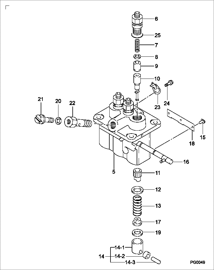
| 000. | [01] | 09450-08480 | PUMP ASSY, INJECTI | 31B6505050 |
| 005. | [01] | 09011-06110 | HOUSING SUB-ASSY, | 47X0123600 |
| 006. | [03] | 09013-00450 | HOLDER SUB-ASSY, D | 47X0113200 |
| 007. | [03] | 09013-61100 | SPRING, DELIVERY V | 47X0113300 |
| 008. | [03] | 09013-70130 | GASKET, DELIVERY V | |
| 009. | [03] | 09014-02610 | VALVE SUB-ASSY, IN | 47X0107700 |
| 010. | [03] | 09015-05550 | ELEMENT SUB-ASSY, | 47X0105400 |
| 011. | [03] | 09016-10210 | SLEEVE, PLUNGER CO | |
| 012. | [03] | 09016-30082 | SEAT, SPRING, UPR | MM501098 |
| 013. | [03] | 09016-40170 | SPRING, PUMP PLUNG | |
| 014. | [03] | 09017-00170 | TAPPET SUB-ASSY,IN | EZ01775027 |
| 014-001. | [03] | 09017-10022 | TAPPET, INJECTION | |
| 014-002. | [03] | 09017-60020 | PIN, INJECTION PUM | |
| 014-003. | [03] | 09217-60010 | ROLLER, FEED PUMP | 09217-60010 |
| 015. | [03] | 09018-30050 | PIN, INJECTION PUM | |
| 016. | [01] | 09021-00470 | RACK ASSY, CONTROL | |
| 017. | [03] | 09030-10060 | SEAT, SPRING, LWR | EZ0177514 |
| 018. | [01] | 09046-70040 | PLATE | |
| 019. | [3C] | 09031-10010 | PLATE, TAPPET ADJU | 09031-10010 |
| 019. | [3C] | 09031-10310 | PLATE, TAPPET ADJU | |
| 019. | [3C] | 09031-10300 | PLATE, TAPPET ADJU | |
| 019. | [3C] | 09031-10280 | PLATE, TAPPET ADJU | |
| 019. | [3C] | 09031-10170 | PLATE, TAPPET ADJU | FR51530028 |
| 019. | [3C] | 09031-10160 | PLATE, TAPPET ADJU | FR51530027 |
| 019. | [3C] | 09031-10140 | PLATE, TAPPET ADJU | 09031-10140 |
| 019. | [3C] | 09031-10130 | PLATE, TAPPET ADJU | 09031-10130 |
| 019. | [3C] | 09031-10120 | PLATE, TAPPET ADJU | 09031-10120 |
| 019. | [3C] | 09031-10110 | PLATE, TAPPET ADJU | 09031-10110 |
| 020. | [01] | 94901-81020 | WASHER, COPPER PLA | 94901-81020 |
| 021. | [01] | 09024-40180 | SCREW, AIR BLEEDER | MM501152 |
| 022. | [01] | 94918-00510 | SCREW, HOLLOW | MM500083 |
| 023. | [02] | 09006-80020 | PLATE, ADJUSTING | |
| 024. | [02] | 94904-80800 | BOLT, WASHER HEAD | MM514195 |
| 025. | [03] | 09013-90410 | O-RING | 47X0122700 |
Include in #3:
09450-08480
as PUMP ASSY, INJECTI
Cross reference number
| Part num | Firm num | Firm | Name |
| 09450-08480 | 31B6505050 | PUMP ASSY, INJECTI | |
| 31B6505050 | MITSUBISHI | PUMP ASSY, INJECTI |
Information:
INJECTION NOZZLE (Right side illustrated)
1. Lines (eight, four each side). 2. Injection nozzles (eight, four each side). 3. Clamps (eight, four each side).4. Remove the adapter (4) and lift injection nozzle (2) out of the cylinder head.
ADAPTER AND NOZZLE REMOVAL
2. Injection nozzle. 4. Adapter. 5. O-ring seal. 6. O-ring seal.
Pull nozzle straight out, by hand, to remove. Slight twisting action is permissible if necessary. Never pry out a nozzle with a screwdriver or other similar tool.
Always replace O-ring seals (5) and (6) before installing nozzle.5. Use needle-nose pliers to remove carbon seal dam (8). Always install a new compression seal (7) and carbon seal dam (8) before installing injection nozzle.
REMOVING CARBON SEAL DAM (Typical Example)
7. Compression seal. 8. Carbon seal dam.Install Fuel Injection Nozzles
1. Be sure the bore in the cylinder head and fuel inlet fittings are clean.
Never install an injection nozzle that has been dropped, without first testing it with the 8S2242 Nozzle Tester Group. The injector tips are very hard and brittle and break easily.
2. Install a new compression seal and carbon seal dam. Use carbon seal dam installation tool (9) to install the carbon seal dam.
INSTALLING CARBON SEAL DAM (Typical Example)
9. 8S2252 Carbon Seal Dam Installation Tool.3. Install a new O-ring seal (6) on the injection nozzle (2) and a new O-ring seal (5) on the adapter (4).4. Install the injection nozzle (2) into the cylinder head using a twisting motion. Do not use lubricant in the cylinder head bore or on the nozzle body.
INSTALLING NOZZLE
2. Injection nozzle. 4. Adapter. 5. O-ring seal. 6. O-ring seal.
Do not bend the injector inlet connection when installing injector into cylinder head. Bending of the inlet connection creates tension on the injector and causes binding of the needle in the guide.
5. Install the adapter (4) and tighten the injection nozzle-to-adapter retaining nut. Tighten retaining nut to 30 5 lb. ft. (4.1 0.7 mkg). Hand tighten the fuel injection line.6. Install the injection nozzle clamp.7. Install the fuel return manifold and rocker arm assembly. Install retaining bolts and locks. Tighten bolts to 18 5 lb. ft. (2.5 0.7 mkg) and bend locks.8. Adjust the intake valve clearance to .015 in. (0.38 mm) and the exhaust valve clearance to .025 in. (0.64 mm).9. Install valve cover. Install mounting bolts and tighten to 120 24 lb. in. (138 28 cm.kg).10. Purge the fuel lines of air by motoring the engine until fuel, free of air, flows from the connections.11. Use 5P144 Fuel Line Socket to tighten the fuel line connections to 30 5 lb. ft. (4.1 0.7 mkg).12. Start the engine and correct any fuel leaks that may occur.