Information pump assy, injecti
Nozzle:
0935007910
Rating:
Components :
| 001. | PUMP ASSY, INJECTI | 09450-08240 |
Scheme ###:
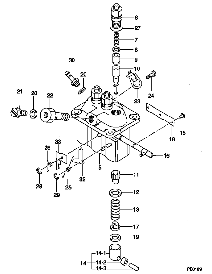
| 000. | [01] | 09450-08240 | PUMP ASSY, INJECTI | 30H6506800 |
| 005. | [01] | 09011-05980 | HOUSING SUB-ASSY, | 47X0117900 |
| 006. | [03] | 09013-00450 | HOLDER SUB-ASSY, D | 47X0113200 |
| 007. | [03] | 09013-61100 | SPRING, DELIVERY V | 47X0113300 |
| 008. | [03] | 09013-70130 | GASKET, DELIVERY V | |
| 009. | [03] | 09014-02610 | VALVE SUB-ASSY, IN | 47X0107700 |
| 010. | [03] | 09015-06580 | ELEMENT SUB-ASSY, | 47X0117000 |
| 011. | [03] | 09016-10210 | SLEEVE, PLUNGER CO | |
| 012. | [03] | 09016-30082 | SEAT, SPRING, UPR | MM501098 |
| 013. | [03] | 09016-40170 | SPRING, PUMP PLUNG | |
| 014. | [03] | 09217-60010 | ROLLER, FEED PUMP | 09217-60010 |
| 014. | [03] | 09017-60020 | PIN, INJECTION PUM | |
| 014. | [03] | 09017-10022 | TAPPET, INJECTION | |
| 014. | [03] | 09017-00170 | TAPPET SUB-ASSY,IN | EZ01775027 |
| 015. | [03] | 09018-30050 | PIN, INJECTION PUM | |
| 016. | [01] | 09021-00470 | RACK ASSY, CONTROL | |
| 017. | [03] | 09030-10060 | SEAT, SPRING, LWR | EZ0177514 |
| 018. | [01] | 09046-70040 | PLATE | |
| 019. | [3C] | 09031-10310 | PLATE, TAPPET ADJU | |
| 019. | [3C] | 09031-10300 | PLATE, TAPPET ADJU | |
| 019. | [3C] | 09031-10280 | PLATE, TAPPET ADJU | |
| 019. | [3C] | 09031-10170 | PLATE, TAPPET ADJU | FR51530028 |
| 019. | [3C] | 09031-10160 | PLATE, TAPPET ADJU | FR51530027 |
| 019. | [3C] | 09031-10140 | PLATE, TAPPET ADJU | 09031-10140 |
| 019. | [3C] | 09031-10130 | PLATE, TAPPET ADJU | 09031-10130 |
| 019. | [3C] | 09031-10120 | PLATE, TAPPET ADJU | 09031-10120 |
| 019. | [3C] | 09031-10110 | PLATE, TAPPET ADJU | 09031-10110 |
| 019. | [3C] | 09031-10010 | PLATE, TAPPET ADJU | 09031-10010 |
| 020. | [02] | 94901-81020 | WASHER, COPPER PLA | 94901-81020 |
| 021. | [01] | 09024-40180 | SCREW, AIR BLEEDER | MM501152 |
| 022. | [01] | 94918-00510 | SCREW, HOLLOW | MM500083 |
| 023. | [02] | 09006-80020 | PLATE, ADJUSTING | |
| 024. | [02] | 94904-80800 | BOLT, WASHER HEAD | MM514195 |
| 025. | [01] | 09055-40470 | SPRING, DIAPHRAGM | |
| 026. | [01] | 09055-40390 | SPRING, DIAPHRAGM | |
| 027. | [03] | 90802-20150 | O-RING | |
| 027. | [03] | 09013-90410 | O-RING | 47X0122700 |
| 028. | [01] | 09089-40020 | E-RING | MM501496 |
| 029. | [01] | 09089-40010 | E-RING | 09089-40010 |
| 030. | [01] | 09314-10260 | NIPPLE, OIL LEAKAG | |
| 032. | [1C] | 09021-97270 | STOPPER | 47X0115800 |
| 032. | [1C] | 09021-97280 | STOPPER | 47X0115900 |
| 032. | [1C] | 09021-97290 | STOPPER | 47X0116000 |
| 032. | [1C] | 09021-97300 | STOPPER | 47X0116100 |
| 032. | [1C] | 09021-97310 | STOPPER | 47X0116200 |
| 032. | [1C] | 09021-97260 | STOPPER | 47X0121500 |
| 032. | [1C] | 09021-95370 | STOPPER | |
| 032. | [1C] | 09021-95360 | STOPPER | MM501747 |
| 032. | [1C] | 09021-93120 | STOPPER | |
| 032. | [1C] | 09021-93110 | STOPPER | |
| 032. | [1C] | 09021-93100 | STOPPER | |
| 032. | [1C] | 09021-93090 | STOPPER | |
| 032. | [1C] | 09021-93080 | STOPPER | |
| 033. | [1C] | 09021-97350 | STOPPER | 47X0120800 |
| 033. | [1C] | 09021-97340 | STOPPER | 47X0120700 |
| 033. | [1C] | 09021-97330 | STOPPER | 47X0120600 |
| 033. | [1C] | 09021-97320 | STOPPER | 47X0120500 |
| 033. | [1C] | 09021-95830 | STOPPER | MM514012 |
| 033. | [1C] | 09021-97360 | STOPPER | 47X0120900 |
| 033. | [1C] | 09021-97370 | STOPPER | 47X0121000 |
| 033. | [1C] | 09021-97380 | STOPPER | 47X0121100 |
| 033. | [1C] | 09021-97390 | STOPPER | 47X0121200 |
| 033. | [1C] | 09021-97400 | STOPPER | 47X0121800 |
| 033. | [1C] | 09021-97410 | STOPPER | 47X0121900 |
| 033. | [1C] | 09021-97420 | STOPPER | 47X0122000 |
| 033. | [1C] | 09021-97430 | STOPPER | 47X0123000 |
| 033. | [1C] | 09021-95820 | STOPPER | MM514011 |
| 033. | [1C] | 09021-95810 | STOPPER | MM514010 |
| 033. | [1C] | 09021-93790 | STOPPER | |
| 033. | [1C] | 09021-93800 | STOPPER | |
| 033. | [1C] | 09021-93810 | STOPPER | |
| 033. | [1C] | 09021-93820 | STOPPER | |
| 033. | [1C] | 09021-93830 | STOPPER | |
| 033. | [1C] | 09021-93840 | STOPPER | |
| 033. | [1C] | 09021-93850 | STOPPER | |
| 033. | [1C] | 09021-93860 | STOPPER | |
| 033. | [1C] | 09021-95760 | STOPPER | |
| 033. | [1C] | 09021-95770 | STOPPER | MM514006 |
| 033. | [1C] | 09021-95780 | STOPPER | MM514007 |
| 033. | [1C] | 09021-95790 | STOPPER | MM514008 |
| 033. | [1C] | 09021-95800 | STOPPER | MM514009 |
| 033. | [1C] | 09021-97440 | STOPPER | 47X0123100 |
Include in #3:
09450-08240
as PUMP ASSY, INJECTI
Cross reference number
| Part num | Firm num | Firm | Name |
| 09450-08240 | 30H6506800 | PUMP ASSY, INJECTI | |
| 30H6506800 | MITSUBISHI | PUMP ASSY, INJECTI |
Information:
start by:remove turbocharger 1. Install turbocharger in tool group (A). Put marks on th three housings of the turbocharger for correct installation and alignment at assembly. Remove "V" clamp (2) and compressor housing (1). 2. Remove "V" clamp (3). Remove the cartridge housing (5) from the turbine housing (4). 3. Install tool (C) in tool (B) and put the cartridge assembly in tool (C) as shown. Use tool (D) to remove the nut that holds compressor wheel (6).
When the nut is loosened, do not put a side force on the shaft.
The oil used to heat the compressor wheel must have a flash point (the temperature at which the oil will burn) above 400°F (204°C).
4. Install tool (H) on tool (E). Heat tool (E) to a temperature of 350°F (177°C). Install the cartridge assembly on tool (H) so that only the compressor wheel is in the oil. Heat the compressor wheel for no more than 10 minutes.
Do not let the turbine wheel hit the bottom of the press.
5. Install tool (H) on tool (G). Put the cartridge assembly in tool (H) as shown. Remove compressor wheel (6) with an arbor press and tool (F). Step 5 must be done before the compressor wheel becomes cooler. 6. Put the turbine wheel in tool (C). Remove seal ring (8) and shroud (7) from the shaft. 7. Bend the tabs of the locks from bolts (10) and remove the bolts and locks.8. Remove backplate assembly (11) from the cartridge housing. Remove spacer (9) from backplate assembly (11). Remove the seal rings from spacer (9).9. Remove the collar from behind backplate assembly (11). 10. Remove thrust bearing (13) and O-ring seal (12) from the cartridge housing. 11. Remove top bearing (14) and the washer from the cartridge housing. Put a long dye mark on the top face of bearing (14). 12. Use tool (J) and remove the two rings that hold top and bottom bearings in position. Remove the bottom bearing and washer. Put a short dye mark on the bearing. The dye marks are used for identification of the bearings when they are installed.13. Use tool (J) and remove the last ring that holds the bottom bearing in position from the cartridge housing.14. Check all the parts of the turbocharger for damage. If the parts have damage, use new parts for replacement. See SPECIAL INSTRUCTION FORM NO. SMHS6854 for TURBOCHARGER RECONDITIONING. Also see GUIDELINE FOR REUSABLE PARTS FORM NO. SEBF8018.Assemble Turbocharger (Airesearch TV81)
1. Make sure that all of the oil passages in the turbocharger cartridge housing are clean and free of dirt and foreign material.2. Put clean engine oil on all parts of the cartridge assembly.
Rings (1), (4) and (5) must be installed with the round edge of the rings toward the bearings.
3. Install ring (4) in the