Information pump assy, injecti
Nozzle:
0935006790
Rating:
Components :
| 001. | PUMP ASSY, INJECTI | 09450-08230 |
Scheme ###:
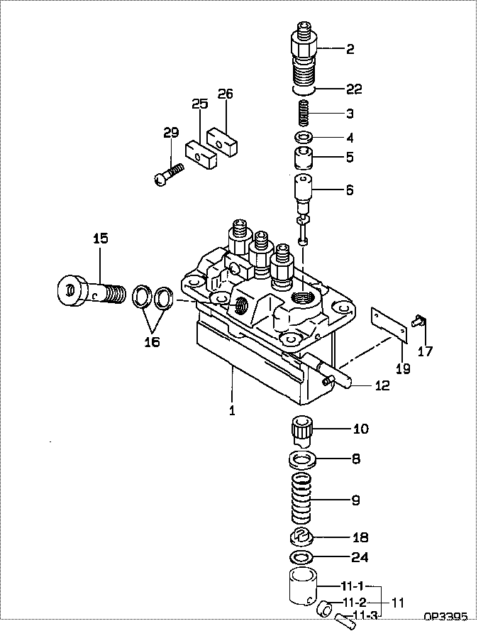
| 000. | [01] | 09450-08230 | PUMP ASSY, INJECTI | 1G548-51011 |
| 001. | [01] | 09011-05260 | HOUSING SUB-ASSY, | |
| 002. | [04] | 09013-00450 | HOLDER SUB-ASSY, D | 16415-51221 |
| 003. | [04] | 09013-61100 | SPRING, DELIVERY V | 16454-51231 |
| 004. | [04] | 09013-70130 | GASKET, DELIVERY V | 11420-51241 |
| 005. | [04] | 09014-00410 | VALVE SUB-ASSY, IN | 15221-51031 |
| 006. | [04] | 09015-06710 | ELEMENT SUB-ASSY, | |
| 008. | [04] | 09016-30082 | SEAT, SPRING, UPR | 15221-51271 |
| 009. | [04] | 09016-40170 | SPRING, PUMP PLUNG | 15221-51281 |
| 010. | [04] | 09016-10520 | SLEEVE, PLUNGER CO | |
| 011. | [04] | 09017-00170 | TAPPET SUB-ASSY,IN | 15221-51071 |
| 011-001. | [04] | 09017-10022 | TAPPET, INJECTION | 15021-51990 |
| 011-002. | [04] | 09217-60010 | ROLLER, FEED PUMP | 15109-52931 |
| 011-003. | [04] | 09017-60020 | PIN, INJECTION PUM | 15021-51970 |
| 012. | [01] | 09021-00850 | RACK ASSY, CONTROL | |
| 015. | [01] | 94918-00310 | SCREW, HOLLOW | 15101-51321 |
| 016. | [02] | 09022-20050 | WASHER, FUEL PIPE | 15401-96652 |
| 017. | [04] | 09018-30050 | PIN, INJECTION PUM | 14611-51251 |
| 018. | [04] | 09030-10060 | SEAT, SPRING, LWR | 15021-51291 |
| 019. | [02] | 09046-70030 | PLATE | 14611-51441 |
| 022. | [04] | 90802-20150 | O-RING | 14611-51201 |
| 022. | [04] | 09013-90410 | O-RING | |
| 024. | [4C] | 09031-10310 | PLATE, TAPPET ADJU | |
| 024. | [4C] | 09031-10300 | PLATE, TAPPET ADJU | |
| 024. | [4C] | 09031-10280 | PLATE, TAPPET ADJU | |
| 024. | [4C] | 09031-10170 | PLATE, TAPPET ADJU | |
| 024. | [4C] | 09031-10160 | PLATE, TAPPET ADJU | |
| 024. | [4C] | 09031-10140 | PLATE, TAPPET ADJU | |
| 024. | [4C] | 09031-10130 | PLATE, TAPPET ADJU | 15221-51491 |
| 024. | [4C] | 09031-10120 | PLATE, TAPPET ADJU | |
| 024. | [4C] | 09031-10110 | PLATE, TAPPET ADJU | |
| 024. | [4C] | 09031-10010 | PLATE, TAPPET ADJU | 14109-51301 |
| 025. | [02] | 09023-10081 | PLATE, DELIVERY VA | |
| 026. | [02] | 09023-20050 | PLATE, DELIVERY VA | |
| 029. | [02] | 94904-44330 | BOLT |
Include in #3:
09450-08230
as PUMP ASSY, INJECTI
Cross reference number
| Part num | Firm num | Firm | Name |
| 09450-08230 | 1G548-5101 | PUMP ASSY, INJECTI | |
| 1G548-51011 | KUBOTA | PUMP ASSY, INJECTI |
Information:
start by:a) remove turbocharger 1. Install turbocharger in tool group (A). Remove "V" clamp (2) and compressor housing (1). 2. Remove "V" clamp (3). Remove the cartridge housing (5) from the turbine housing (4). 3. Put the cartridge housing in tool (B). Use a T-handle (6) and remove the nut that holds compressor wheel (7). Remove the compressor wheel.
When the nut is loosened, do not put a side force on the shaft.
4. Remove the cartridge housing from tool (B). Remove the turbine wheel (9) and shaft from the cartridge housing. Remove seal ring (8) from the shaft. 5. Remove the snap ring that holds insert (10) in the cartridge housing. Remove the insert with tooling (C). 6. Remove the sleeve (13) from the insert (11). Remove the two seal rings (12) from the insert. 7. Remove deflector (14), ring (16), sleeve (15), bearing (18) and ring (17) from the cartridge housing. If the oil hole is not open this will cause a bearing failure. 8. Remove the snap ring that holds bearing (19) in the cartridge housing. Remove bearing (19). Remove snap ring (20) with tool (D). 9. Remove the snap ring that holds bearing (21) in place with tool (D). Remove bearing (21) and sleeve (22) from the cartridge housing. 10. Turn the cartridge housing over. Remove snap ring (23). Remove shroud (24). 11. Remove snap ring (25) from the cartridge housing with tool (D).12. Inspect all parts and install new parts as needed.Assemble Turbocharger (Schwitzer F522)
1. Make sure all oil passages are open and clean. Put engine oil on all parts before assembly. 2. Install snap ring (1) in the cartridge housing with tool (A). Install the snap rings with the round side toward the bearing. 3. Install shroud (4) on the housing. Turn the shroud to make sure it is down on the housing even. The high part (2) on the housing will keep the shroud in position on the housing after assembly.4. Install the snap ring (3). 5. Turn the cartridge housing over. Install sleeve (6) and bearing (5). Install the snap ring that holds bearing (6) in the cartridge housing with tool (A). 6. Install snap ring (8) with tool (A). Install bearing (7). Install the snap ring that holds bearing (7) in place. Install the snap rings with the round side toward the bearing. 7. Install ring (12), bearing (13), sleeve (10), ring (11) and deflector (9) in the housing.
The oil hole in bearing (13) must be open and clean.
8. Install seal rings (15) in sleeve (16). Install the sleeve in insert (14). 9. Check O-ring seal (17). Make a replacement of the seal if necessary. Install insert (18) in the cartridge housing (19). Install the snap ring to hold the insert in place. The flat side of the snap ring must be toward the insert. Put 6V2055 High Vacuum Grease in the groove for seal ring (20) at assembly to one half or more of the depth of the groove all