Information pump assy, injecti
Nozzle:
0935005070
Rating:
Components :
| 001. | PUMP ASSY, INJECTI | 09450-08150 |
Scheme ###:
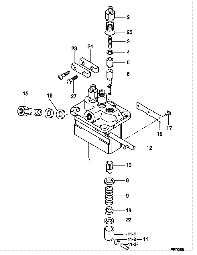
| 000. | [01] | 09450-08150 | PUMP ASSY, INJECTI | 1G733-51011 |
| 001. | [01] | 09011-05950 | HOUSING SUB-ASSY, | |
| 002. | [03] | 09013-00450 | HOLDER SUB-ASSY, D | 16415-51221 |
| 003. | [03] | 09013-61100 | SPRING, DELIVERY V | 16454-51231 |
| 004. | [03] | 09013-70130 | GASKET, DELIVERY V | 11420-51241 |
| 005. | [03] | 09014-02310 | VALVE SUB-ASSY, IN | 16454-51031 |
| 006. | [03] | 09015-05150 | ELEMENT SUB-ASSY, | |
| 008. | [03] | 09016-30082 | SEAT, SPRING, UPR | 15221-51271 |
| 009. | [03] | 09016-40170 | SPRING, PUMP PLUNG | 15221-51281 |
| 010. | [03] | 09016-10210 | SLEEVE, PLUNGER CO | 15221-51382 |
| 011. | [03] | 09017-00170 | TAPPET SUB-ASSY,IN | 15221-51071 |
| 011-001. | [03] | 09017-10022 | TAPPET, INJECTION | 15021-51990 |
| 011-002. | [03] | 09217-60010 | ROLLER, FEED PUMP | 15109-52931 |
| 011-003. | [03] | 09017-60020 | PIN, INJECTION PUM | 15021-51970 |
| 012. | [01] | 09021-00220 | RACK ASSY, CONTROL | 15321-51061 |
| 015. | [01] | 09024-50160 | SCREW, HOLLOW | 15521-51321 |
| 016. | [02] | 09024-10010 | WASHER, AIR BLEEDE | 15221-96651 |
| 017. | [03] | 09018-30050 | PIN, INJECTION PUM | 14611-51251 |
| 018. | [03] | 09030-10060 | SEAT, SPRING, LWR | 15021-51291 |
| 019. | [01] | 09046-70040 | PLATE | 19484-51461 |
| 020. | [03] | 90802-20150 | O-RING | 14611-51201 |
| 020. | [03] | 09013-90410 | O-RING | |
| 022. | [3C] | 09031-10530 | PLATE, TAPPET ADJU | |
| 022. | [3C] | 09031-10520 | PLATE, TAPPET ADJU | |
| 022. | [3C] | 09031-10510 | PLATE, TAPPET ADJU | |
| 022. | [3C] | 09031-10500 | PLATE, TAPPET ADJU | |
| 022. | [3C] | 09031-10490 | PLATE, TAPPET ADJU | |
| 022. | [3C] | 09031-10060 | PLATE, TAPPET ADJU | |
| 022. | [3C] | 09031-10050 | PLATE, TAPPET ADJU | |
| 022. | [3C] | 09031-10040 | PLATE, TAPPET ADJU | |
| 022. | [3C] | 09031-10030 | PLATE, TAPPET ADJU | |
| 022. | [3C] | 09031-10020 | PLATE, TAPPET ADJU | |
| 023. | [01] | 09023-10070 | PLATE, DELIVERY VA | |
| 024. | [01] | 09023-20070 | PLATE, DELIVERY VA | |
| 027. | [02] | 94904-44330 | BOLT |
Include in #3:
09450-08150
as PUMP ASSY, INJECTI
Cross reference number
| Part num | Firm num | Firm | Name |
| 09450-08150 | 1G733-5101 | PUMP ASSY, INJECTI | |
| 1G733-51011 | KUBOTA | PUMP ASSY, INJECTI |
Information:
start by:a) separation of governor from fuel injection pump housing 1. Remove the protection caps and felt washers (1) from pumps.2. Use wrench (A) to remove bushings (2) that hold the fuel injection pumps into the housing. Remove seals (3).3. Use extractor (B) to remove the pumps from the pump housing. Put identification on the injection pumps as to their location in the pump housing.4. Remove bonnet (4), ring (5), spring (6) and check valve (7) from barrel (8).5. Remove plunger assembly (11), washer (10) and spring (9) from the barrel.
Be careful not to cause damage to plunger assemblies. Keep the same cylinder pump and plunger together, the plunger from one pump can not be installed in another group.
6. Remove rack (12) from the housing. 7. Remove spacers (13) and lifters (14) from the housing. Keep the spacers and lifters together with identification as to their location in the pump housing. 8. Remove two bolts (16), lock and two sleeves from the gear assembly.9. Remove gear assembly (15) from the camshaft. 10. Remove two bolts, plate (17) and the spacer that hold the camshaft in position in the pump housing. 11. Remove the camshaft from the pump housing. 12. Use tool group (C) to remove the camshaft bearings from the pump housing.13. Remove the bearings for the fuel rack from the pump housing.Assemble Fuel Injection Pump Housing
1. Use tooling (C) to install the camshaft bearings in the fuel injection pump housing. Install the camshaft bearing joints 15° from the vertical centerline of the bores. Install the front and rear camshaft bearings even with the fuel injection pump housing. Install the center camshaft bearing a distance of 4.81 .02 in. (122.2 0.5 mm) from the rear face of the fuel injection pump housing. 2. Use tooling (F) to install the bearing with a tab for the groove in the rack.3. Use tooling (E) to install the rear bearing for the rack. Install the bearing to a depth of .282 .005 in. (7.16 0.13 mm). The small holes in the rear bearing must be installed parallel to the vertical centerline of the pump. 4. Put clean engine oil on the camshaft. Install the camshaft in the pump housing. 5. Install the spacer, plate (1) and two bolts that hold the camshaft in place in the pump housing. 6. Put gear assembly (2) in position on the end of the camshaft. Be sure rod (3) is in the groove of the camshaft. 7. Install sleeves (4), lock and two bolts on the gear assembly. 8. Install spacers (5) with their respective lifters (6) in the pump housing. If new lifters and/or pumps are to be installed, make adjustment of the fuel pump timing dimension. See SETTING THE INJECTION PUMP TIMING DIMENSION: OFF ENGINE TESTING AND ADJUSTING. 9. Install rack (7) in the pump housing.10. Assemble the fuel injection pumps as follows: a) Put clean fuel on all parts.b) Install the spring, washers and plunger in the