Information pump assy, injecti
Nozzle:
0935003840

Rating:
Compare Prices: .
As an associate, we earn commssions on qualifying purchases through the links below

Aftermarket Fuel Injection Pump 094500-7040 094500-8130 Fit Intended For Engine L3E
Generic Motorcycle Parts || Heavy Equipment Parts || Spare Parts || Final Drives
Generic Motorcycle Parts || Heavy Equipment Parts || Spare Parts || Final Drives

Fuel Injection Pump 094500-7040 094500-8130 for Mitsubishi Engine L3E
100% Apollo part number:094500-7040 094500-8130 || application: for Mitsubishi Engine L3E
100% Apollo part number:094500-7040 094500-8130 || application: for Mitsubishi Engine L3E

Components :
| 001. | PUMP ASSY, INJECTI | 09450-08130 |
Scheme ###:
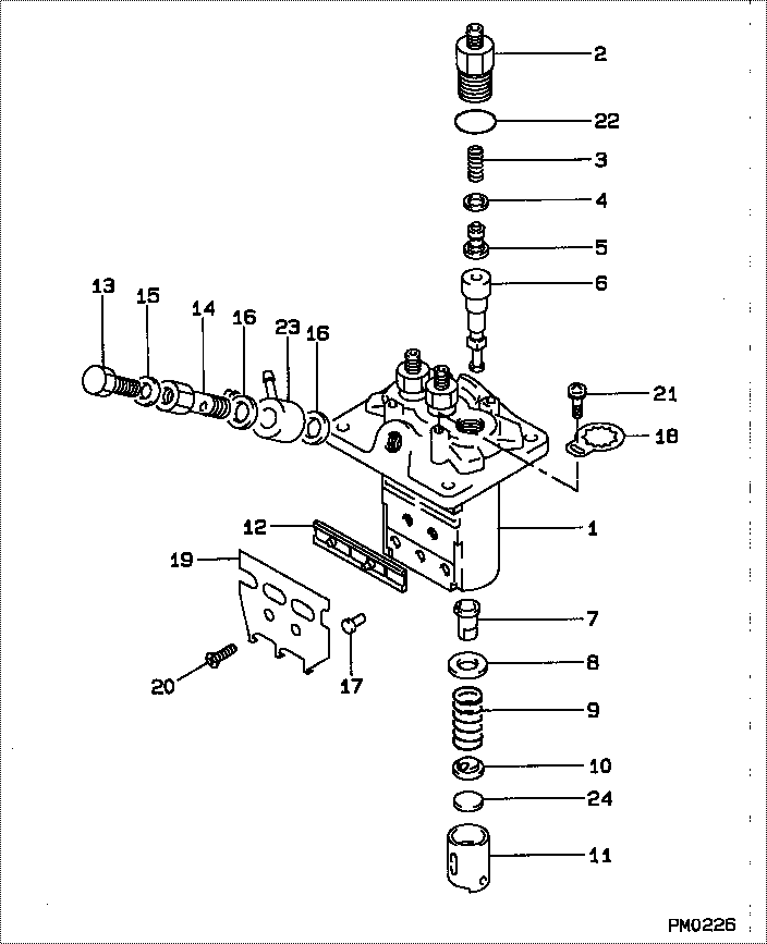
| 000. | [01] | 09450-08130 | PUMP ASSY, INJECTI | 30L6502700 |
| 001. | [01] | 09011-03730 | HOUSING SUB-ASSY, | |
| 002. | [03] | 09013-00390 | HOLDER SUB-ASSY, D | 47X0119800 |
| 003. | [03] | 09013-60530 | SPRING, DELIVERY V | |
| 004. | [03] | 09013-70130 | GASKET, DELIVERY V | |
| 005. | [03] | 09014-02110 | VALVE SUB-ASSY, IN | |
| 006. | [03] | 09015-04280 | ELEMENT SUB-ASSY, | |
| 007. | [03] | 09016-00140 | SLEEVE SUB-ASSY, C | |
| 008. | [03] | 09016-30140 | SEAT, SPRING, UPR | |
| 009. | [03] | 09016-40220 | SPRING, PUMP PLUNG | MM501926 |
| 010. | [03] | 09016-50170 | SEAT, SPRING, LWR | |
| 011. | [03] | 09017-00220 | TAPPET SUB-ASSY,IN | |
| 012. | [01] | 09021-00560 | RACK ASSY, CONTROL | |
| 013. | [01] | 09024-40010 | SCREW, AIR BLEEDER | 09024-40010 |
| 014. | [01] | 09024-50310 | SCREW, HOLLOW | |
| 015. | [01] | 09024-80010 | WASHER, DRAIN SCRE | 09024-80010 |
| 016. | [02] | 09025-10010 | WASHER, INJECTION | 85265-00077 |
| 017. | [03] | 09018-30090 | PIN, INJECTION PUM | |
| 018. | [03] | 09023-00070 | PLATE SET, VALVE H | |
| 019. | [01] | 09069-11020 | BRACKET, STOP WIRE | |
| 020. | [02] | 94900-20500 | SCREW, COUNTERSUNK | |
| 021. | [03] | 94900-75390 | SCREW, W/WASHER | |
| 022. | [03] | 90801-10130 | O-RING | |
| 022. | [03] | 09013-90400 | O-RING | 47X0122600 |
| 023. | [01] | 09221-70590 | NIPPLE, SWIVEL | |
| 024. | [3C] | 09031-10400 | PLATE, TAPPET ADJU | |
| 024. | [3C] | 09031-10410 | PLATE, TAPPET ADJU | |
| 024. | [3C] | 09031-10420 | PLATE, TAPPET ADJU | |
| 024. | [3C] | 09031-10430 | PLATE, TAPPET ADJU | |
| 024. | [3C] | 09031-10440 | PLATE, TAPPET ADJU | |
| 024. | [3C] | 09031-10390 | PLATE, TAPPET ADJU | |
| 024. | [3C] | 09031-10380 | PLATE, TAPPET ADJU | |
| 024. | [3C] | 09031-10370 | PLATE, TAPPET ADJU | |
| 024. | [3C] | 09031-10360 | PLATE, TAPPET ADJU | |
| 024. | [3C] | 09031-10350 | PLATE, TAPPET ADJU | |
| 024. | [3C] | 09031-10340 | PLATE, TAPPET ADJU | |
| 024. | [3C] | 09031-10330 | PLATE, TAPPET ADJU | |
| 024. | [3C] | 09031-10320 | PLATE, TAPPET ADJU | |
| 024. | [3C] | 09031-10450 | PLATE, TAPPET ADJU |
Include in #3:
09450-08130
as PUMP ASSY, INJECTI
Cross reference number
| Part num | Firm num | Firm | Name |
| 09450-08130 | 30L6502700 | PUMP ASSY, INJECTI | |
| 30L6502700 | MITSUBISHI | PUMP ASSY, INJECTI |
Information:
start by:a) remove fuel shutoff solenoidb) remove fuel ratio control1. Make a setting of the fuel injection pump timing as follows: a) Turn the engine clockwise (as seen from the front of the engine) with tool (B) to top center of the compression stroke of No. 1 piston. See FINDING TOP CENTER COMPRESSION POSITION FOR NO. 1 PISTON in TESTING AND ADJUSTING. b) Remove the plug from the side of fuel injection pump housing. Install tool (A) through the hole in pump housing and into the notch in the injection pump camshaft. If tool (A) can not be installed in the notch of the injection pump camshaft, the injection pump is not in time with the engine and the following procedure must be followed: a) Remove nuts (1). Remove cover (2) for the automatic timing advance.b) Loosen bolt (3) and hit the bolt with a soft hammer to loosen the automatic timing advance. c) Remove bolt (3) and washer (4). Install the bolt again.d) Turn the fuel injection pump drive shaft clockwise with bolt (3) until tool (A) can be put into the notch in the injection pump camshaft.e) Remove the bolt. Install washer (4) and bolt (3) so the washer is loose.
TYPICAL EXAMPLEf) Remove the timing bolt from the flywheel. Turn the engine 60° counterclockwise (as seen from the front of the engine) with tool (B).g) Tighten the bolt that holds the automatic timing advance by hand. Turn the engine clockwise (as seen from the front of the engine) with tool (B) until the engine is at top center compression stroke of No. 1 piston.h) Tighten bolt (3) to a torque of 15 lb.ft. (20 N m). Remove tool (A) from the fuel injection pump housing. Tighten bolt (3) to a torque of 110 10 lb.ft. (149 14 N m).
Do not tighten the bolt to final torque until tool (A) is removed.
i) Turn the crankshaft counterclockwise (as seen from the front of the engine) two complete revolutions and check the timing to see that timing is correct.j) If timing is not correct, do the above procedure again.k) Install the cover for the automatic timing advance and the nuts that hold it. 2. Disconnect fuel lines (5) and (7) from the fuel injection pump housing.3. Disconnect fuel injection lines (9) from the fuel injection pump housing. Install caps and plugs in all fuel line openings.4. Remove two bolts (8) that hold bracket (6) to the governor housing. 5. Fasten a nylon strap and a hoist to the fuel injection pump housing. Remove bolts (12) and (10) that hold the fuel injection pump housing to the cylinder block.6. Remove bolts (11) that hold the fuel injection pump housing to the fuel injection pump and governor drive housing.7. Remove fuel injection pump housing and governor. The weight is 70 lb. (32 kg).Remove Fuel Injection Pump Housing And Governor (Later)
start by:a) remove fuel shutoff solenoidb) remove fuel ratio control1. Make a setting of the fuel injection pump timing as