Information pump assy, injecti
Nozzle:
0935004320
Rating:
Components :
| 001. | PUMP ASSY, INJECTI | 09450-07640 |
Scheme ###:
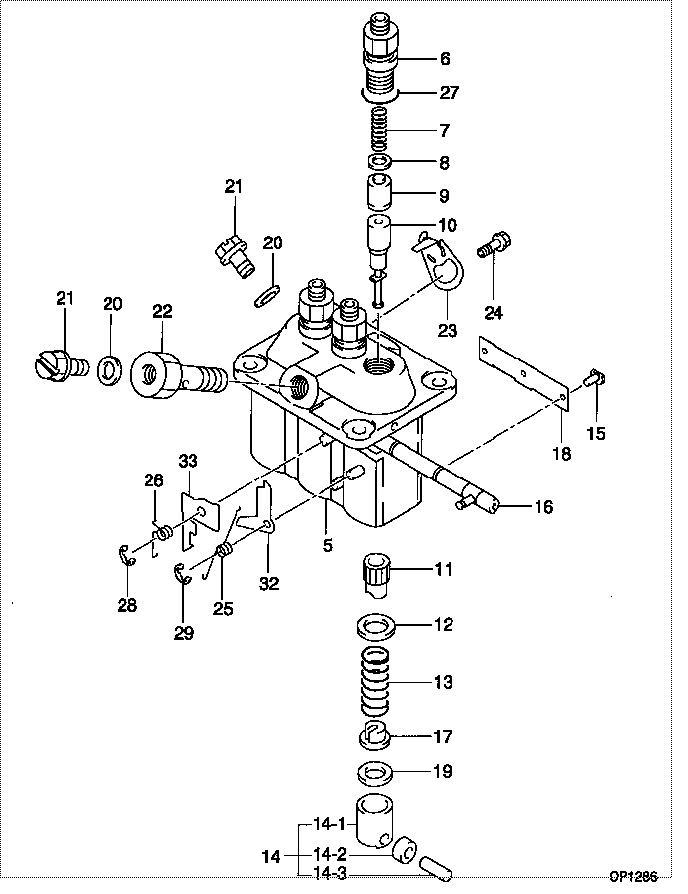
| 000. | [01] | 09450-07640 | PUMP ASSY, INJECTI | 30H6505100 |
| 005. | [01] | 09011-02830 | HOUSING SUB-ASSY, | |
| 006. | [03] | 09013-10720 | HOLDER, DELIVERY V | |
| 007. | [03] | 09013-60940 | SPRING, DELIVERY V | |
| 008. | [03] | 09013-70130 | GASKET, DELIVERY V | |
| 009. | [03] | 09014-02730 | VALVE SUB-ASSY, IN | 47X0115600 |
| 010. | [03] | 09015-04650 | ELEMENT SUB-ASSY, | |
| 011. | [03] | 09016-10210 | SLEEVE, PLUNGER CO | |
| 012. | [03] | 09016-30082 | SEAT, SPRING, UPR | MM501098 |
| 013. | [03] | 09016-40170 | SPRING, PUMP PLUNG | |
| 014. | [03] | 09017-00170 | TAPPET SUB-ASSY,IN | EZ01775027 |
| 014-001. | [03] | 09017-10022 | TAPPET, INJECTION | |
| 014-002. | [03] | 09217-60010 | ROLLER, FEED PUMP | 09217-60010 |
| 014-003. | [03] | 09017-60020 | PIN, INJECTION PUM | |
| 015. | [03] | 09018-30050 | PIN, INJECTION PUM | |
| 016. | [01] | 09021-00470 | RACK ASSY, CONTROL | |
| 017. | [03] | 09030-10060 | SEAT, SPRING, LWR | EZ0177514 |
| 018. | [01] | 09046-70040 | PLATE | |
| 019. | [3C] | 09031-10310 | PLATE, TAPPET ADJU | |
| 019. | [3C] | 09031-10300 | PLATE, TAPPET ADJU | |
| 019. | [3C] | 09031-10280 | PLATE, TAPPET ADJU | |
| 019. | [3C] | 09031-10170 | PLATE, TAPPET ADJU | FR51530028 |
| 019. | [3C] | 09031-10160 | PLATE, TAPPET ADJU | FR51530027 |
| 019. | [3C] | 09031-10140 | PLATE, TAPPET ADJU | 09031-10140 |
| 019. | [3C] | 09031-10130 | PLATE, TAPPET ADJU | 09031-10130 |
| 019. | [3C] | 09031-10120 | PLATE, TAPPET ADJU | 09031-10120 |
| 019. | [3C] | 09031-10110 | PLATE, TAPPET ADJU | 09031-10110 |
| 019. | [3C] | 09031-10010 | PLATE, TAPPET ADJU | 09031-10010 |
| 020. | [02] | 94901-81020 | WASHER, COPPER PLA | 94901-81020 |
| 021. | [02] | 09024-40180 | SCREW, AIR BLEEDER | |
| 022. | [01] | 94918-00510 | SCREW, HOLLOW | MM500083 |
| 023. | [02] | 09006-80020 | PLATE, ADJUSTING | |
| 024. | [02] | 94904-80800 | BOLT, WASHER HEAD | MM514195 |
| 025. | [01] | 09055-40470 | SPRING, DIAPHRAGM | |
| 026. | [01] | 09055-40280 | SPRING, DIAPHRAGM | |
| 027. | [03] | 90802-20150 | O-RING | |
| 027. | [03] | 09013-90410 | O-RING | 47X0122700 |
| 028. | [01] | 09089-40020 | E-RING | MM501496 |
| 029. | [01] | 09089-40010 | E-RING | 09089-40010 |
| 032. | [1C] | 09021-97270 | STOPPER | 47X0115800 |
| 032. | [1C] | 09021-97280 | STOPPER | 47X0115900 |
| 032. | [1C] | 09021-97290 | STOPPER | 47X0116000 |
| 032. | [1C] | 09021-97300 | STOPPER | 47X0116100 |
| 032. | [1C] | 09021-97310 | STOPPER | 47X0116200 |
| 032. | [1C] | 09021-97260 | STOPPER | |
| 032. | [1C] | 09021-95370 | STOPPER | |
| 032. | [1C] | 09021-95360 | STOPPER | MM501747 |
| 032. | [1C] | 09021-93120 | STOPPER | |
| 032. | [1C] | 09021-93110 | STOPPER | |
| 032. | [1C] | 09021-93100 | STOPPER | |
| 032. | [1C] | 09021-93090 | STOPPER | |
| 032. | [1C] | 09021-93080 | STOPPER | |
| 033. | [1C] | 09021-93710 | STOPPER | |
| 033. | [1C] | 09021-93720 | STOPPER | MM501274 |
| 033. | [1C] | 09021-93730 | STOPPER | 47X0115700 |
| 033. | [1C] | 09021-93740 | STOPPER | |
| 033. | [1C] | 09021-93750 | STOPPER | |
| 033. | [1C] | 09021-93760 | STOPPER | |
| 033. | [1C] | 09021-93700 | STOPPER | MM501273 |
| 033. | [1C] | 09021-93690 | STOPPER | |
| 033. | [1C] | 09021-93680 | STOPPER | |
| 033. | [1C] | 09021-93670 | STOPPER | |
| 033. | [1C] | 09021-93660 | STOPPER | |
| 033. | [1C] | 09021-93650 | STOPPER | |
| 033. | [1C] | 09021-93640 | STOPPER | |
| 033. | [1C] | 09021-93630 | STOPPER | |
| 033. | [1C] | 09021-93770 | STOPPER |
Include in #3:
09450-07640
as PUMP ASSY, INJECTI
Cross reference number
| Part num | Firm num | Firm | Name |
| 09450-07640 | 30H6505100 | PUMP ASSY, INJECTI | |
| 30H6505100 | MITSUBISHI | PUMP ASSY, INJECTI |
Information:
3. Remove cylinder liners (1) with tooling (A).Install Cylinder Liners
1. Clean the cylinder liners (3) and the liner bores in the cylinder block.2. Install the cylinder liners in the block without the O-ring seals or filler bands.3. Check the cylinder liner projection as follows: a) Install the S1589 Bolts (2) and 1S379 Washers of tooling (B) on the cylinder block next to each liner. Tighten the bolts evenly, in four steps: 10 lb. ft. (14 N m), 25 lb. ft. (35 N m), 50 lb. ft. (70 N m) and 70 lb. ft. (95 N m).b) Put adapter plate on top of the liner and install the remainder of tooling (B). Tighten the 1D4595 Bolts (1) evenly in four steps: 5 lb. ft. (7 N m), 15 lb. ft. (20 N m), 25 lb. ft. (35 N m) and 50 lb. ft. (70 N m).c) Check to be sure the distance from the bottom edge of the crossbar to the top of the cylinder block is the same on both sides of the liner.d) Check the cylinder liner projection with tool group (C) at four locations around the liner.e) Liner projection must be .0013 to .0069 in. (0.033 to 0.175 mm). Measurements on the same liner must not be different by more than .002 in. (0.05 mm). Average measurements between liners next to each other must not be different by more than .002 in. (0.05 mm). The maximum permissible difference between average projection of all cylinder liners under one cylinder head is .004 in. (0.10 mm). If the liner is turned in the bore, it can make a difference in the liner projection.4. If the liner projection is not .0013 to .0069 in. (0.033 to 0.175 mm), check the thickness of the following parts: spacer plate, spacer plate gasket and cylinder liner flange. The thickness of the spacer plate must be .3925 .0010 in. (9.970 0.025 mm). The thickness of the spacer plate gasket must be .0082 .0010 in. (0.208 0.025 mm). The thickness of the cylinder liner flange must be .4048 .0008 in. (10.282 0.020 mm). If the liner projection changes from point to point around the liner, turn the liner to a new position in the bore. If the liner projection is still not to specifications, move the liner to a different bore.5. When the cylinder projection is correct, put a mark on the liner and block so the liner can be installed in the same position from which it was removed. Cylinder liner projection can be adjusted by the removal of material from (machining) the contact face of the cylinder block with the use of the 8S3140 Cylinder Block Counterboring Tool Arrangement. Machine to a minimum depth of .030 in. (0.76 mm) and to a maximum depth of .045 in. (1.14 mm). The instructions for the use of the tool group are in Special Instruction Form No. FM055228. Shims are available for the adjustment of the liner projection. See
1. Clean the cylinder liners (3) and the liner bores in the cylinder block.2. Install the cylinder liners in the block without the O-ring seals or filler bands.3. Check the cylinder liner projection as follows: a) Install the S1589 Bolts (2) and 1S379 Washers of tooling (B) on the cylinder block next to each liner. Tighten the bolts evenly, in four steps: 10 lb. ft. (14 N m), 25 lb. ft. (35 N m), 50 lb. ft. (70 N m) and 70 lb. ft. (95 N m).b) Put adapter plate on top of the liner and install the remainder of tooling (B). Tighten the 1D4595 Bolts (1) evenly in four steps: 5 lb. ft. (7 N m), 15 lb. ft. (20 N m), 25 lb. ft. (35 N m) and 50 lb. ft. (70 N m).c) Check to be sure the distance from the bottom edge of the crossbar to the top of the cylinder block is the same on both sides of the liner.d) Check the cylinder liner projection with tool group (C) at four locations around the liner.e) Liner projection must be .0013 to .0069 in. (0.033 to 0.175 mm). Measurements on the same liner must not be different by more than .002 in. (0.05 mm). Average measurements between liners next to each other must not be different by more than .002 in. (0.05 mm). The maximum permissible difference between average projection of all cylinder liners under one cylinder head is .004 in. (0.10 mm). If the liner is turned in the bore, it can make a difference in the liner projection.4. If the liner projection is not .0013 to .0069 in. (0.033 to 0.175 mm), check the thickness of the following parts: spacer plate, spacer plate gasket and cylinder liner flange. The thickness of the spacer plate must be .3925 .0010 in. (9.970 0.025 mm). The thickness of the spacer plate gasket must be .0082 .0010 in. (0.208 0.025 mm). The thickness of the cylinder liner flange must be .4048 .0008 in. (10.282 0.020 mm). If the liner projection changes from point to point around the liner, turn the liner to a new position in the bore. If the liner projection is still not to specifications, move the liner to a different bore.5. When the cylinder projection is correct, put a mark on the liner and block so the liner can be installed in the same position from which it was removed. Cylinder liner projection can be adjusted by the removal of material from (machining) the contact face of the cylinder block with the use of the 8S3140 Cylinder Block Counterboring Tool Arrangement. Machine to a minimum depth of .030 in. (0.76 mm) and to a maximum depth of .045 in. (1.14 mm). The instructions for the use of the tool group are in Special Instruction Form No. FM055228. Shims are available for the adjustment of the liner projection. See