Information pump assy, injecti
Nozzle:
0935004540
Rating:
Components :
| 001. | PUMP ASSY, INJECTI | 09450-07560 |
Scheme ###:
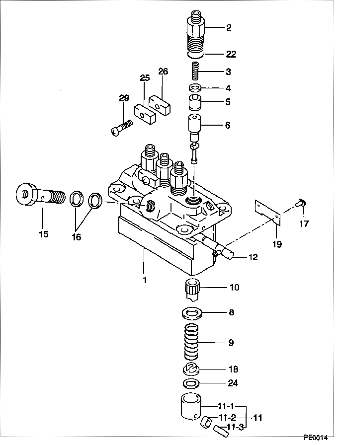
| 000. | [01] | 09450-07560 | PUMP ASSY, INJECTI | 1G628-51011 |
| 001. | [01] | 09011-05420 | HOUSING SUB-ASSY, | |
| 002. | [04] | 09013-00450 | HOLDER SUB-ASSY, D | 16415-51221 |
| 003. | [04] | 09013-60970 | SPRING, DELIVERY V | 16475-51231 |
| 004. | [04] | 09013-70130 | GASKET, DELIVERY V | 11420-51241 |
| 005. | [04] | 09014-02050 | VALVE SUB-ASSY, IN | 16475-51031 |
| 006. | [04] | 09015-05310 | ELEMENT SUB-ASSY, | 17182-51051 |
| 008. | [04] | 09016-30082 | SEAT, SPRING, UPR | 15221-51271 |
| 009. | [04] | 09016-40170 | SPRING, PUMP PLUNG | 15221-51281 |
| 010. | [04] | 09016-10520 | SLEEVE, PLUNGER CO | |
| 011. | [04] | 09017-00170 | TAPPET SUB-ASSY,IN | 15221-51071 |
| 011-001. | [04] | 09017-10022 | TAPPET, INJECTION | 15021-51990 |
| 011-002. | [04] | 09217-60010 | ROLLER, FEED PUMP | 15109-52931 |
| 011-003. | [04] | 09017-60020 | PIN, INJECTION PUM | 15021-51970 |
| 012. | [01] | 09021-00680 | RACK ASSY, CONTROL | |
| 015. | [01] | 09024-50170 | SCREW, HOLLOW | 15471-51321 |
| 016. | [02] | 09022-20050 | WASHER, FUEL PIPE | 15401-96652 |
| 017. | [04] | 09018-30050 | PIN, INJECTION PUM | 14611-51251 |
| 018. | [04] | 09030-10060 | SEAT, SPRING, LWR | 15021-51291 |
| 019. | [02] | 09046-70030 | PLATE | 14611-51441 |
| 022. | [04] | 90802-20150 | O-RING | 14611-51201 |
| 022. | [04] | 09013-90410 | O-RING | |
| 024. | [4C] | 09031-10530 | PLATE, TAPPET ADJU | |
| 024. | [4C] | 09031-10520 | PLATE, TAPPET ADJU | |
| 024. | [4C] | 09031-10510 | PLATE, TAPPET ADJU | |
| 024. | [4C] | 09031-10500 | PLATE, TAPPET ADJU | |
| 024. | [4C] | 09031-10490 | PLATE, TAPPET ADJU | |
| 024. | [4C] | 09031-10060 | PLATE, TAPPET ADJU | |
| 024. | [4C] | 09031-10050 | PLATE, TAPPET ADJU | |
| 024. | [4C] | 09031-10040 | PLATE, TAPPET ADJU | |
| 024. | [4C] | 09031-10030 | PLATE, TAPPET ADJU | |
| 024. | [4C] | 09031-10020 | PLATE, TAPPET ADJU | |
| 025. | [02] | 09023-10081 | PLATE, DELIVERY VA | |
| 026. | [02] | 09023-20050 | PLATE, DELIVERY VA | |
| 029. | [02] | 94904-44330 | BOLT |
Include in #3:
09450-07560
as PUMP ASSY, INJECTI
Cross reference number
| Part num | Firm num | Firm | Name |
| 09450-07560 | 1G628-5101 | PUMP ASSY, INJECTI | |
| 1G628-51011 | KUBOTA | PUMP ASSY, INJECTI |
Information:
3. Remove the water temperature regulator bypass water line (1).4. Disconnect the water inlet line from the bottom of the water pump. Disconnect the linkage for the governor.5. Disconnect the water supply line for the aftercooler.6. Install a 3/8"-16 NC forged eyebolt in the top of the water pump. Fasten a hoist to the water pump (2). Remove the bolts that hold the water pump to the engine and the engine oil cooler. Remove the water pump. Weight of the pump is 70 lb. (32 kg).Install Water Pump
1. Fasten a hoist to the water pump (1). Put the pump in position on the engine.2. Install the bolts that hold the water pump to the engine. Install the bolts (2) that fasten the water pump to the oil cooler.3. Install the water lines to the aftercooler and water temperature regulator housing.4. Install and adjust the drive belts on the water pump drive pulley. See LUBRICATION AND MAINTENANCE GUIDE.5. Fill the engine with oil and coolant to the correct levels.Disassemble Water
start by:a) remove water pump 1. Remove the pulley retaining nut and lock. Install tool (A) and remove the pulley. Remove the key.2. Remove the retainer and seal. Remove seal from retainer.3. Remove the cover retaining bolts and nuts. Remove the cover from the water pump housing. 4. Remove the impeller retaining nut. Remove the impeller (1) as the shaft is held and the impeller is turned clockwise.5. Remove the shaft assembly (2) from the housing. Remove the bearing assemblies and spacer from the shaft.6. Remove the carbon seal assembly and lip type seal from the housing.Assemble Water Pump
1. Use tool (A) to install the carbon seal assembly into water pump housing. Install the lip type seal in housing with lip of seal toward bearing assemblies. Put lubrication on the lip of seal with lubricant to be sealed.2. Install the bearing assemblies and spacer on the shaft. Install the shaft assembly in housing.3. Install the seal in the cage with lip of seal toward bearing assemblies. Put lubrication the lip of seal. Install the cage on the housing. 4. Install the pulley, lock and retaining nut. Tighten nut (2) to 100 10 lb.ft. (135.6 13.6 N m) and bend the lock.5. Install the impeller on shaft. Adjust impeller clearance (3) to .010 .005 in. (0.25 0.13 mm). Install the impeller retaining nut (1) and tighten to 50-55 lb. ft. (67.8-76.4 N m). After nut is tightened, hit the pulley end of shaft and check impeller clearance while impeller is turned.6. Install the water pump cover, retaining bolts and nuts.end by:a) install water pump