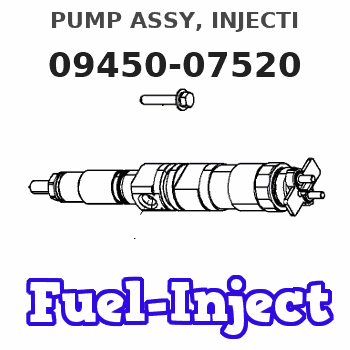
Information pump assy, injecti
Nozzle:
0935005060
Rating:
Compare Prices: .
As an associate, we earn commssions on qualifying purchases through the links below

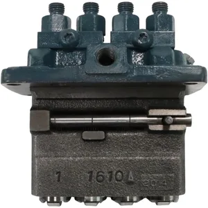
094500-7520 094500-7521 Fuel Injection Pump Suitable for Kubota V1903 V2203 V2403 V2403-M Engine KX161-2S Excavator L4330 L4610 L4630 L4740 L5030 M4800 MX5000 Tractor
OfkZynodor Part Name:Fuel Injection Pump || Part Number:094500-7520 094500-7521 || Application:Suitable for Kubota V1903 V2203 V2403 V2403-M Engine KX161-2S Excavator L4330 L4610 L4630 L4740 L5030 M4800 MX5000 Tractor || Please make sure to carefully compare the photos and check the part numbers before making the purchase. If you are unable to confirm your engine model or part number, please leave us a message and we will assist you in confirming that the product you purchase is the one you need. || Your order is not merely a single purchase but the beginning of a cooperative journey, aiming to ensure the safe and smooth operation of your vehicle. We are proud to offer you reliable precision engineering components and unparalleled services.
OfkZynodor Part Name:Fuel Injection Pump || Part Number:094500-7520 094500-7521 || Application:Suitable for Kubota V1903 V2203 V2403 V2403-M Engine KX161-2S Excavator L4330 L4610 L4630 L4740 L5030 M4800 MX5000 Tractor || Please make sure to carefully compare the photos and check the part numbers before making the purchase. If you are unable to confirm your engine model or part number, please leave us a message and we will assist you in confirming that the product you purchase is the one you need. || Your order is not merely a single purchase but the beginning of a cooperative journey, aiming to ensure the safe and smooth operation of your vehicle. We are proud to offer you reliable precision engineering components and unparalleled services.

WZCNLXLX Fuel Injection Pump 1G762-51010 1G762-51012 094500-7520 For Kubota V2203 V2403 Engine
WZCNLXLX Item Name:Fuel Injection Pump || Item Number: 094500-7520, 094500-7521, 1G762-51010,1G76251010, 1G762-51012,1G76251012, 1G762-51011,1G76251011, 0945007520, 0945007521, 094500-5840, 0945005840, 7023148 || Application:For Kubota V2203 V2403 Engine || Note: If you are unsure if the product is suitable.In order not to delay your use of the parts, please provide your engine nameplate or serial number and part number, and we will help you confirm if it is suitable. To avoid unnecessary returns, please check the product image and part number to ensure it is the product you want. || Tip: Please contact us - we are a professional sales team and we have many products to offer to you. Many buyers are very satisfied with our service. You can get first-class products and high-quality services from us, believe me, you will have a pleasant shopping experience here.
WZCNLXLX Item Name:Fuel Injection Pump || Item Number: 094500-7520, 094500-7521, 1G762-51010,1G76251010, 1G762-51012,1G76251012, 1G762-51011,1G76251011, 0945007520, 0945007521, 094500-5840, 0945005840, 7023148 || Application:For Kubota V2203 V2403 Engine || Note: If you are unsure if the product is suitable.In order not to delay your use of the parts, please provide your engine nameplate or serial number and part number, and we will help you confirm if it is suitable. To avoid unnecessary returns, please check the product image and part number to ensure it is the product you want. || Tip: Please contact us - we are a professional sales team and we have many products to offer to you. Many buyers are very satisfied with our service. You can get first-class products and high-quality services from us, believe me, you will have a pleasant shopping experience here.

094500-7520 094500-7521 Fuel Injection Pump for Kubota V2203 V2403 V2403-M Engine:
OfkZynodor Part Number 094500-7520 094500-7521 || Application:For Kubota Excavator KX121-2 KX161-2; Tractor L3710DT L3940DT L3940HSTC L4240DT L4300DT L4300F L4310DT L4310F, L4400F L4630D MX4700F MX4700H MX5000DT MX5000F MX5000SU || This engine model is suitable for Kubota V2203, V2403, and V2403-M engines. || Please make sure to carefully compare the photos and check the part numbers before making the purchase. If you are unable to confirm your engine model or part number, please leave us a message and we will assist you in confirming that the product you purchase is the one you need. || Your order is not merely a single purchase but the beginning of a cooperative journey, aiming to ensure the safe and smooth operation of your vehicle. We are proud to offer you reliable precision engineering components and unparalleled services.
OfkZynodor Part Number 094500-7520 094500-7521 || Application:For Kubota Excavator KX121-2 KX161-2; Tractor L3710DT L3940DT L3940HSTC L4240DT L4300DT L4300F L4310DT L4310F, L4400F L4630D MX4700F MX4700H MX5000DT MX5000F MX5000SU || This engine model is suitable for Kubota V2203, V2403, and V2403-M engines. || Please make sure to carefully compare the photos and check the part numbers before making the purchase. If you are unable to confirm your engine model or part number, please leave us a message and we will assist you in confirming that the product you purchase is the one you need. || Your order is not merely a single purchase but the beginning of a cooperative journey, aiming to ensure the safe and smooth operation of your vehicle. We are proud to offer you reliable precision engineering components and unparalleled services.
You can express buy:
USD 821.3
19-05-2025
19-05-2025
Fuel Injection Pump 094500-7520 094500-7521 For Kubota V2203 V2403 L5030 M4800 Tractors Bobcat 331 334 763 773 Excavator Loader
Components :
| 001. | PUMP ASSY, INJECTI | 09450-07520 |
Scheme ###:
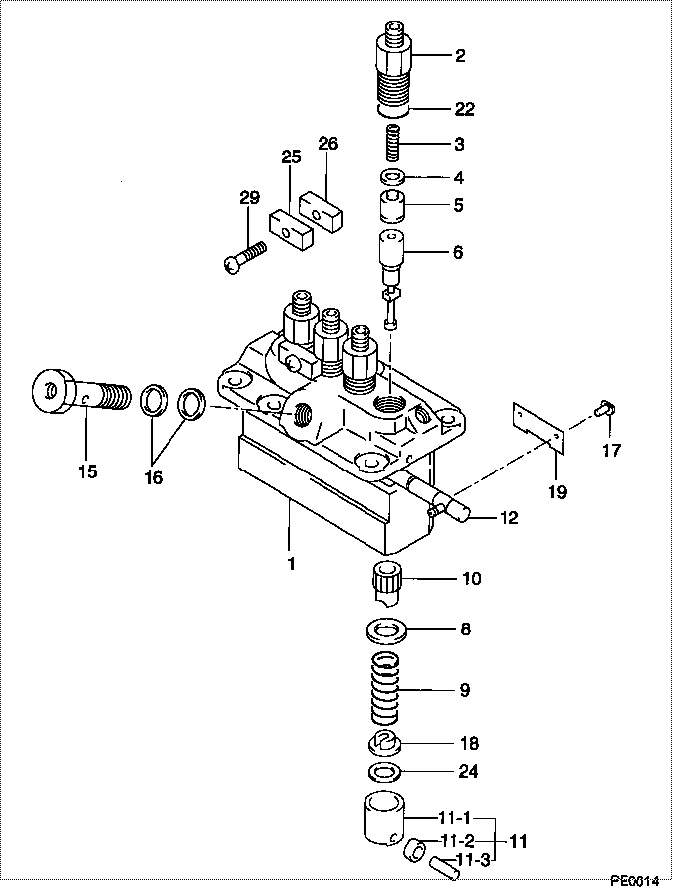
| 000. | [01] | 09450-07520 | PUMP ASSY, INJECTI | 1G762-51011 |
| 001. | [01] | 09011-05420 | HOUSING SUB-ASSY, | |
| 002. | [04] | 09013-00450 | HOLDER SUB-ASSY, D | 16415-51221 |
| 003. | [04] | 09013-61100 | SPRING, DELIVERY V | 16454-51231 |
| 004. | [04] | 09013-70130 | GASKET, DELIVERY V | 11420-51241 |
| 005. | [04] | 09014-02310 | VALVE SUB-ASSY, IN | 16454-51031 |
| 006. | [04] | 09015-05150 | ELEMENT SUB-ASSY, | |
| 008. | [04] | 09016-30082 | SEAT, SPRING, UPR | 15221-51271 |
| 009. | [04] | 09016-40170 | SPRING, PUMP PLUNG | 15221-51281 |
| 010. | [04] | 09016-10210 | SLEEVE, PLUNGER CO | 15221-51382 |
| 011. | [04] | 09017-00170 | TAPPET SUB-ASSY,IN | 15221-51071 |
| 011-001. | [04] | 09017-10022 | TAPPET, INJECTION | 15021-51990 |
| 011-002. | [04] | 09217-60010 | ROLLER, FEED PUMP | 15109-52931 |
| 011-003. | [04] | 09017-60020 | PIN, INJECTION PUM | 15021-51970 |
| 012. | [01] | 09021-00251 | RACK ASSY, CONTROL | 15401-51061 |
| 015. | [01] | 09024-50170 | SCREW, HOLLOW | 15471-51321 |
| 016. | [02] | 09022-20050 | WASHER, FUEL PIPE | 15401-96652 |
| 017. | [04] | 09018-30050 | PIN, INJECTION PUM | 14611-51251 |
| 018. | [04] | 09030-10060 | SEAT, SPRING, LWR | 15021-51291 |
| 019. | [02] | 09046-70030 | PLATE | 14611-51441 |
| 022. | [04] | 90802-20150 | O-RING | 14611-51201 |
| 022. | [04] | 09013-90410 | O-RING | |
| 024. | [4C] | 09031-10530 | PLATE, TAPPET ADJU | |
| 024. | [4C] | 09031-10520 | PLATE, TAPPET ADJU | |
| 024. | [4C] | 09031-10510 | PLATE, TAPPET ADJU | |
| 024. | [4C] | 09031-10500 | PLATE, TAPPET ADJU | |
| 024. | [4C] | 09031-10490 | PLATE, TAPPET ADJU | |
| 024. | [4C] | 09031-10060 | PLATE, TAPPET ADJU | |
| 024. | [4C] | 09031-10050 | PLATE, TAPPET ADJU | |
| 024. | [4C] | 09031-10040 | PLATE, TAPPET ADJU | |
| 024. | [4C] | 09031-10030 | PLATE, TAPPET ADJU | |
| 024. | [4C] | 09031-10020 | PLATE, TAPPET ADJU | |
| 025. | [02] | 09023-10081 | PLATE, DELIVERY VA | |
| 026. | [02] | 09023-20050 | PLATE, DELIVERY VA | |
| 029. | [02] | 94904-44330 | BOLT |
Include in #3:
09450-07520
as PUMP ASSY, INJECTI
Cross reference number
| Part num | Firm num | Firm | Name |
| 09450-07520 | 1G762-5101 | PUMP ASSY, INJECTI | |
| 1G762-51011 | KUBOTA | PUMP ASSY, INJECTI |
Information:
start by: a) remove fuel injection lines 1. Remove cover (1) from the front of the timing gear cover. Remove bolt (2) and washer (3). Install bolt (2) again to the position shown. Use tool (A) to loosen the pump drive gear from the camshaft. Remove tool (A) and bolt (2).2. Remove the governor linkage. Disconnect the fuel supply line. 3. Remove inlet oil tube (4) for the turbocharger.4. Disconnect the air tube from the fuel ratio control.5. Disconnect hose (5).6. Disconnect the three drain tubes from the fuel injection pump housing.7. Remove bracket (6).8. Remove the three nuts that hold the fuel injection pump housing and governor to the timing plate.9. Remove the fuel injection pump housing and governor.Install Fuel Injection Pump Housing And Governor
1. Use the following procedures to put the No. 1 piston at top center on the compression stroke. No. 1 piston at top center (TC) on the compression stroke is the starting point for all timing procedures. The engine is seen from the flywheel end when direction of flywheel rotation is given.a) Turn the flywheel approximately 30 degrees clockwise. The reason for making this step is to be sure the play is removed from the timing gears when the engine is put on top center. b) For engines with a timing pointer, remove the cover on the flywheel housing. Turn the flywheel counterclockwise until the "TC 1" mark on the flywheel is in alignment with the pointer.c) For engines with a timing bolt, turn the flywheel counterclockwise until a 3/8-16 NC bolt can be installed in the flywheel through the hole in the flywheel housing. Do not turn the flywheel backwards.d) Remove the breather from the valve cover. The rocker arms for No. 1 piston can be seen through the breather hole in the valve cover.e) Check to see if both rocker arms for the No. 1 piston can be moved backward and forward by hand. The No. 1 piston is at top center on the compression stroke when the "TC 1" mark on the flywheel is in alignment with the pointer, or the bolt can be put in the flywheel through the hole in the flywheel housing, and both rocker arms for the No. 1 piston can be moved backward and forward by hand. f) If both rocker arms can not be moved by hand, the No. 1 piston is not at top center on the compression stroke. Turn the flywheel counterclockwise one full turn (360°). For engines with a timing pointer, the "TC 1" mark on the flywheel must then be in alignment with the pointer. For engines with a timing bolt, the bolt must be installed in the flywheel through the hole in the flywheel housing.2. For engines with a timing pointer, turn the flywheel counterclockwise until the pointer is between the 1° and 2° mark on the flywheel as shown. 3. For engines with a timing bolt, do not turn the flywheel past this position. 4. Remove the
1. Use the following procedures to put the No. 1 piston at top center on the compression stroke. No. 1 piston at top center (TC) on the compression stroke is the starting point for all timing procedures. The engine is seen from the flywheel end when direction of flywheel rotation is given.a) Turn the flywheel approximately 30 degrees clockwise. The reason for making this step is to be sure the play is removed from the timing gears when the engine is put on top center. b) For engines with a timing pointer, remove the cover on the flywheel housing. Turn the flywheel counterclockwise until the "TC 1" mark on the flywheel is in alignment with the pointer.c) For engines with a timing bolt, turn the flywheel counterclockwise until a 3/8-16 NC bolt can be installed in the flywheel through the hole in the flywheel housing. Do not turn the flywheel backwards.d) Remove the breather from the valve cover. The rocker arms for No. 1 piston can be seen through the breather hole in the valve cover.e) Check to see if both rocker arms for the No. 1 piston can be moved backward and forward by hand. The No. 1 piston is at top center on the compression stroke when the "TC 1" mark on the flywheel is in alignment with the pointer, or the bolt can be put in the flywheel through the hole in the flywheel housing, and both rocker arms for the No. 1 piston can be moved backward and forward by hand. f) If both rocker arms can not be moved by hand, the No. 1 piston is not at top center on the compression stroke. Turn the flywheel counterclockwise one full turn (360°). For engines with a timing pointer, the "TC 1" mark on the flywheel must then be in alignment with the pointer. For engines with a timing bolt, the bolt must be installed in the flywheel through the hole in the flywheel housing.2. For engines with a timing pointer, turn the flywheel counterclockwise until the pointer is between the 1° and 2° mark on the flywheel as shown. 3. For engines with a timing bolt, do not turn the flywheel past this position. 4. Remove the