Information pump assy, injecti
Nozzle:
0935003840
Rating:
Components :
| 001. | PUMP ASSY, INJECTI | 09450-07470 |
Scheme ###:
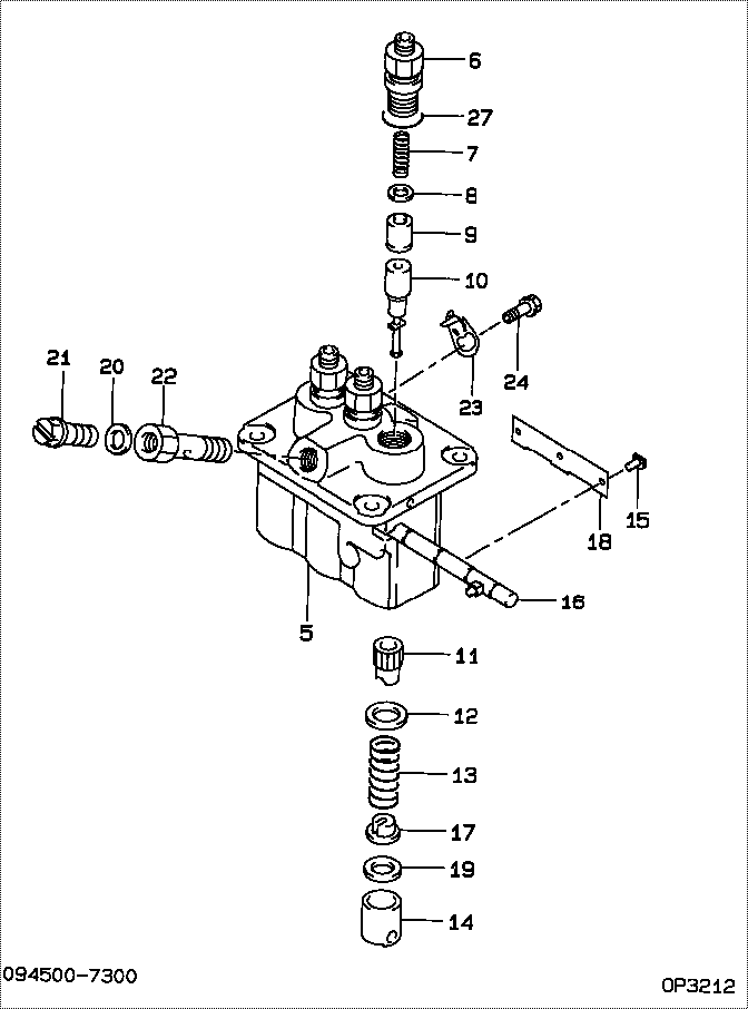
| 000. | [01] | 09450-07470 | PUMP ASSY, INJECTI | 31B6504020 |
| 005. | [01] | 09011-05110 | HOUSING SUB-ASSY, | 47X0106100 |
| 006. | [03] | 09013-10520 | HOLDER, DELIVERY V | |
| 007. | [03] | 09013-60540 | SPRING, DELIVERY V | |
| 008. | [03] | 09013-70130 | GASKET, DELIVERY V | |
| 009. | [03] | 09014-02610 | VALVE SUB-ASSY, IN | 47X0107700 |
| 010. | [03] | 09015-05550 | ELEMENT SUB-ASSY, | 47X0105400 |
| 011. | [03] | 09016-10210 | SLEEVE, PLUNGER CO | |
| 012. | [03] | 09016-30082 | SEAT, SPRING, UPR | MM501098 |
| 013. | [03] | 09016-40170 | SPRING, PUMP PLUNG | |
| 014. | [03] | 09017-00170 | TAPPET SUB-ASSY,IN | EZ01775027 |
| 014-001. | [03] | 09017-10022 | TAPPET, INJECTION | |
| 014-002. | [03] | 09217-60010 | ROLLER, FEED PUMP | 09217-60010 |
| 014-003. | [03] | 09017-60020 | PIN, INJECTION PUM | |
| 015. | [03] | 09018-30050 | PIN, INJECTION PUM | |
| 016. | [01] | 09021-00470 | RACK ASSY, CONTROL | |
| 017. | [03] | 09030-10060 | SEAT, SPRING, LWR | EZ0177514 |
| 018. | [01] | 09046-70040 | PLATE | |
| 019. | [3C] | 09031-10010 | PLATE, TAPPET ADJU | 09031-10010 |
| 019. | [3C] | 09031-10310 | PLATE, TAPPET ADJU | |
| 019. | [3C] | 09031-10300 | PLATE, TAPPET ADJU | |
| 019. | [3C] | 09031-10280 | PLATE, TAPPET ADJU | |
| 019. | [3C] | 09031-10170 | PLATE, TAPPET ADJU | FR51530028 |
| 019. | [3C] | 09031-10160 | PLATE, TAPPET ADJU | FR51530027 |
| 019. | [3C] | 09031-10140 | PLATE, TAPPET ADJU | 09031-10140 |
| 019. | [3C] | 09031-10130 | PLATE, TAPPET ADJU | 09031-10130 |
| 019. | [3C] | 09031-10120 | PLATE, TAPPET ADJU | 09031-10120 |
| 019. | [3C] | 09031-10110 | PLATE, TAPPET ADJU | 09031-10110 |
| 020. | [01] | 94901-81020 | WASHER, COPPER PLA | 94901-81020 |
| 021. | [01] | 09024-40180 | SCREW, AIR BLEEDER | |
| 022. | [01] | 09024-50210 | SCREW, HOLLOW | |
| 023. | [02] | 09006-80020 | PLATE, ADJUSTING | |
| 024. | [02] | 94904-80800 | BOLT, WASHER HEAD | MM514195 |
| 027. | [03] | 90802-20150 | O-RING | |
| 027. | [03] | 09013-90410 | O-RING | 47X0122700 |
Include in #3:
09450-07470
as PUMP ASSY, INJECTI
Cross reference number
| Part num | Firm num | Firm | Name |
| 09450-07470 | 31B6504020 | PUMP ASSY, INJECTI | |
| 31B6504020 | MITSUBISHI | PUMP ASSY, INJECTI |
Information:
1. Turn the crankshaft until the "C" mark on crankshaft gear (2) is in alignment with the "C" mark on camshaft gear (1). 2. Put a mark across the teeth of the fuel pump drive gear and idler gear at location (X). Put a mark across the teeth of the idler gear and camshaft gear at location (Y). The marks are necessary for the correct timing of the camshaft for the fuel injection pump when the crankshaft is installed.3. Fasten a hoist to the crankshaft.4. Remove the caps for the crankshaft main bearings.5. Remove the crankshaft. Weight of the crankshaft is 200 lb. (91 kg).6. Remove the main bearings from the main bearing caps. Remove the crankshaft main bearings from the cylinder block. 7. Use tool (A) to remove the crankshaft gear and the oil seal wear sleeve.Install Crankshaft
1. Clean the bearing surfaces in the cylinder block. Install the upper halves of the main bearings in the block. Put clean SAE 30 engine oil on the bearings.2. Heat the crankshaft gear to a maximum temperature of 601°F (316°C). Install the gear on the crankshaft. Fasten a hoist to the crankshaft and put the crankshaft in position in the cylinder block with all timing marks in alignment.3. Clean the bearing surfaces of the main bearing caps. Install the lower halves of the main bearings in the caps. 4. Install Plastigage (A) on the bearing to check the bearing clearance. See INSTALL CRANKSHAFT MAIN BEARINGS for the correct bearing clearance procedure. The main bearing caps must be installed with the part number toward the front of the block. Make sure the number on the cap is the same number as the number on the left side of each cap saddle. 5. Install thrust plate (1) (bearing) in the No. 7 main bearing. The thrust bearing has a tab that fits into a machined area in the cylinder block. The tab will not let the thrust bearing be installed backward.6. Put clean SAE 30 engine oil on the cap bolt threads, face of the washers and lower halves of the main bearings. Put the caps in position on the engine. Install the bolts and washers. Tighten the bolts to a torque of 30 3 lb.ft. (40 4 N m). Put a mark across the bolt heads and bearing, and tighten the bolts 90° clockwise from the mark. 7. Check the crankshaft end play with tool group (B). End play with new bearings must be .0025 to .0145 in. (0.064 to 0.368 mm). Maximum permissible end play with used bearings is .025 in. (0.64 mm). The crankshaft end play is controlled by the thrust plates (bearings).8. If the fuel pump drive gear, idler gear, or camshaft gear has been removed or if a replacement of the crankshaft gear has been made, it will be necessary to put the engine into time after assembly. See INSTALL FUEL INJECTION PUMP HOUSING AND GOVERNOR.end by:a) install pistonsb) install timing gear coverc) install flywheel housing
1. Clean the bearing surfaces in the cylinder block. Install the upper halves of the main bearings in the block. Put clean SAE 30 engine oil on the bearings.2. Heat the crankshaft gear to a maximum temperature of 601°F (316°C). Install the gear on the crankshaft. Fasten a hoist to the crankshaft and put the crankshaft in position in the cylinder block with all timing marks in alignment.3. Clean the bearing surfaces of the main bearing caps. Install the lower halves of the main bearings in the caps. 4. Install Plastigage (A) on the bearing to check the bearing clearance. See INSTALL CRANKSHAFT MAIN BEARINGS for the correct bearing clearance procedure. The main bearing caps must be installed with the part number toward the front of the block. Make sure the number on the cap is the same number as the number on the left side of each cap saddle. 5. Install thrust plate (1) (bearing) in the No. 7 main bearing. The thrust bearing has a tab that fits into a machined area in the cylinder block. The tab will not let the thrust bearing be installed backward.6. Put clean SAE 30 engine oil on the cap bolt threads, face of the washers and lower halves of the main bearings. Put the caps in position on the engine. Install the bolts and washers. Tighten the bolts to a torque of 30 3 lb.ft. (40 4 N m). Put a mark across the bolt heads and bearing, and tighten the bolts 90° clockwise from the mark. 7. Check the crankshaft end play with tool group (B). End play with new bearings must be .0025 to .0145 in. (0.064 to 0.368 mm). Maximum permissible end play with used bearings is .025 in. (0.64 mm). The crankshaft end play is controlled by the thrust plates (bearings).8. If the fuel pump drive gear, idler gear, or camshaft gear has been removed or if a replacement of the crankshaft gear has been made, it will be necessary to put the engine into time after assembly. See INSTALL FUEL INJECTION PUMP HOUSING AND GOVERNOR.end by:a) install pistonsb) install timing gear coverc) install flywheel housing