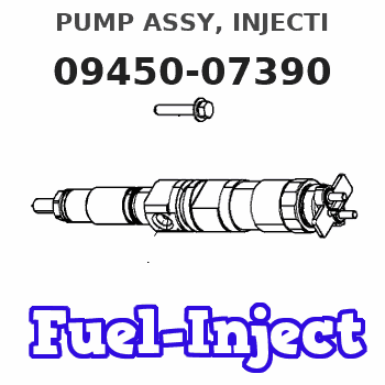
Information pump assy, injecti
Nozzle:
0935005060
Rating:
Compare Prices: .
As an associate, we earn commssions on qualifying purchases through the links below

$865.00
21 Nov 2024
CN: IMELBUFF Excavator P
IMELBUFF 1G610-51010 1G610-51011 094500-7390 Fuel Injection Pump for Kubota V2003 V2003T Engine Bobcat Skid Steer Loader 743 763 773 7763 S150 S160 S175 S185 T180 T190 Excavator 331 337
IMELBUFF 🚜Part Number: 1G610-51010 1G610-51011 094500-7390 || 🚜Engine Model: for Kubota Engine V2003 V2003-T-E2B-AUSA-1 V2003T || 🚜Vehicle Application: for Bobcat Skid Steer Loader 743 763 773 7763 S150 S160 S175 S185 T180 T190 Excavator 331 337 || 🚜Warm Tips: Please check your part numbers before placing an order. If you are not sure, you can send us your engine model or fuel pump part number || 🚜Service: 5-months warranty and 24 hour support for customer service. Please feel free to contact us by email if you have any question with the product
IMELBUFF 🚜Part Number: 1G610-51010 1G610-51011 094500-7390 || 🚜Engine Model: for Kubota Engine V2003 V2003-T-E2B-AUSA-1 V2003T || 🚜Vehicle Application: for Bobcat Skid Steer Loader 743 763 773 7763 S150 S160 S175 S185 T180 T190 Excavator 331 337 || 🚜Warm Tips: Please check your part numbers before placing an order. If you are not sure, you can send us your engine model or fuel pump part number || 🚜Service: 5-months warranty and 24 hour support for customer service. Please feel free to contact us by email if you have any question with the product
Components :
| 001. | PUMP ASSY, INJECTI | 09450-07390 |
Scheme ###:
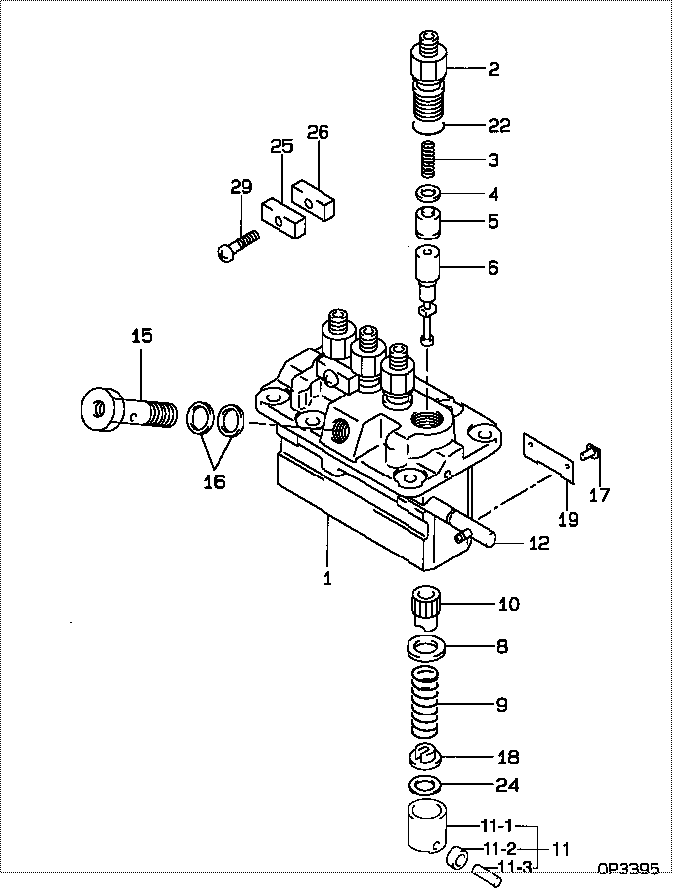
| 000. | [01] | 09450-07390 | PUMP ASSY, INJECTI | 1G610-51011 |
| 001. | [01] | 09011-05420 | HOUSING SUB-ASSY, | |
| 002. | [04] | 09013-00450 | HOLDER SUB-ASSY, D | 16415-51221 |
| 003. | [04] | 09013-61100 | SPRING, DELIVERY V | 16454-51231 |
| 004. | [04] | 09013-70130 | GASKET, DELIVERY V | 11420-51241 |
| 005. | [04] | 09014-02310 | VALVE SUB-ASSY, IN | 16454-51031 |
| 006. | [04] | 09015-05150 | ELEMENT SUB-ASSY, | |
| 008. | [04] | 09016-30082 | SEAT, SPRING, UPR | 15221-51271 |
| 009. | [04] | 09016-40170 | SPRING, PUMP PLUNG | 15221-51281 |
| 010. | [04] | 09016-10210 | SLEEVE, PLUNGER CO | 15221-51382 |
| 011. | [04] | 09017-00170 | TAPPET SUB-ASSY,IN | 15221-51071 |
| 011-001. | [04] | 09017-10022 | TAPPET, INJECTION | 15021-51990 |
| 011-002. | [04] | 09217-60010 | ROLLER, FEED PUMP | 15109-52931 |
| 011-003. | [04] | 09017-60020 | PIN, INJECTION PUM | 15021-51970 |
| 012. | [01] | 09021-00251 | RACK ASSY, CONTROL | 15401-51061 |
| 015. | [01] | 09024-50170 | SCREW, HOLLOW | 15471-51321 |
| 016. | [02] | 09022-20050 | WASHER, FUEL PIPE | 15401-96652 |
| 017. | [04] | 09018-30050 | PIN, INJECTION PUM | 14611-51251 |
| 018. | [04] | 09030-10060 | SEAT, SPRING, LWR | 15021-51291 |
| 019. | [02] | 09046-70030 | PLATE | 14611-51441 |
| 022. | [04] | 90802-20150 | O-RING | 14611-51201 |
| 022. | [04] | 09013-90410 | O-RING | |
| 024. | [4C] | 09031-10530 | PLATE, TAPPET ADJU | |
| 024. | [4C] | 09031-10520 | PLATE, TAPPET ADJU | |
| 024. | [4C] | 09031-10510 | PLATE, TAPPET ADJU | |
| 024. | [4C] | 09031-10500 | PLATE, TAPPET ADJU | |
| 024. | [4C] | 09031-10490 | PLATE, TAPPET ADJU | |
| 024. | [4C] | 09031-10060 | PLATE, TAPPET ADJU | |
| 024. | [4C] | 09031-10050 | PLATE, TAPPET ADJU | |
| 024. | [4C] | 09031-10040 | PLATE, TAPPET ADJU | |
| 024. | [4C] | 09031-10030 | PLATE, TAPPET ADJU | |
| 024. | [4C] | 09031-10020 | PLATE, TAPPET ADJU | |
| 025. | [02] | 09023-10081 | PLATE, DELIVERY VA | |
| 026. | [02] | 09023-20050 | PLATE, DELIVERY VA | |
| 029. | [02] | 94904-44330 | BOLT |
Include in #3:
09450-07390
as PUMP ASSY, INJECTI
Cross reference number
| Part num | Firm num | Firm | Name |
| 09450-07390 | 1G610-5101 | PUMP ASSY, INJECTI | |
| 1G610-51011 | KUBOTA | PUMP ASSY, INJECTI |
Information:
1. Remove four bolts (1) that hold the oil pump to the engine block.2. Remove the oil pump. Be careful not to drop the oil pump drive gear.Install Oil Pump
1. Put the oil pump in position on the engine and install the bolts and washers. Make sure the idler gear teeth are correctly engaged with the crankshaft gear. The timing marks on the oil pump idler gear are for four cylinder engines with balancers.end by: a) install oil panDisassemble Oil Pump
start by:a) remove oil pump 1. Remove two bolts (1) and locks. Remove suction bell assembly (2). 2. Remove oil pump idler gear (3). 3. Use tool (A) to remove the idler gear bearing. 4. Remove the bolt and washer from the oil pump drive gear. Use tool (B) to remove the drive gear. Remove the key from the shaft. 5. Remove cover assembly (4). 6. Use tool (A) to remove the two bearings from the cover assembly. 7. Remove the two gears and shaft assemblies. Remove bolt (5). Remove valve assembly (6). 8. Use tool (A) to remove the two bearings from the cover assembly.Assemble Oil Pump
1. Use tool (A) to install two bearings each in the body assembly and the cover assembly. 2. Install valve assembly (2) with bolt (1). Install the two gears and shaft assemblies. Put oil on the two gears and make sure the gears move freely. 3. Install cover (3).4. Install the key on the shaft. Use the bolt and washer to install the oil pump drive gear. Make sure the key and gear groove are in alignment. 5. Use tool (A) to install the idler gear bearing.6. Install the oil pump idler gear. 7. Install bell assembly (4) with the two bolts and locks.end by:a) install oil pump