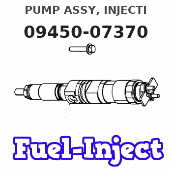
Information pump assy, injecti
Nozzle:
0935003840
Rating:
Compare Prices: .
As an associate, we earn commssions on qualifying purchases through the links below

$1,955.00
02 Oct 2023
CN: Nancy-Parts store
XYohykai Fuel Injection Pump 16427-51010 1642751010 for Kubota L2500 L2900 Tractor D1403 D1503 D1703 Engine
XYohykai ◆Part Name◆:Fuel Injection Pump || ◆Part Number◆:16427-51010 1642751010 || ◆Application◆:for Kubota L2500 L2900 Tractor D1403 D1503 D1703 Engine || ◆Notice◆-Application information provided is for reference only. Please confirm the part number and compare old parts before purchase. If you have any question,pls feel free to ask us. || ◆Worth Choice◆-This product has stable performance, high reliability, easy installation and fast response.
XYohykai ◆Part Name◆:Fuel Injection Pump || ◆Part Number◆:16427-51010 1642751010 || ◆Application◆:for Kubota L2500 L2900 Tractor D1403 D1503 D1703 Engine || ◆Notice◆-Application information provided is for reference only. Please confirm the part number and compare old parts before purchase. If you have any question,pls feel free to ask us. || ◆Worth Choice◆-This product has stable performance, high reliability, easy installation and fast response.

$835.00
27 Feb 2024
CN: Nancy-Parts store
XYohykai 0445020037 CP3 Fuel Injection Pump 0445020105 0986437332 for 6.6 Diesel LBZ Truck Engine
XYohykai 0445020037 CP3 0445020105 0986437332 || Fuel Injection Pump || For 6.6 Diesel LBZ Truck Engine
XYohykai 0445020037 CP3 0445020105 0986437332 || Fuel Injection Pump || For 6.6 Diesel LBZ Truck Engine

$850.00
02 Oct 2023
CN: Nancy-Parts store
XYohykai Fuel Injection Pump 094500-7370 0945007370 For Diesel Engine parts
XYohykai
XYohykai
Components :
| 001. | PUMP ASSY, INJECTI | 09450-07370 |
Scheme ###:
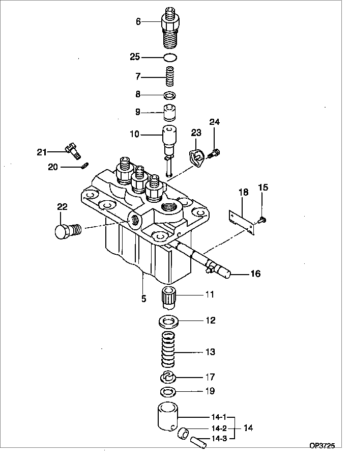
| 000. | [01] | 09450-07370 | PUMP ASSY, INJECTI | 31A6504030 |
| 005. | [01] | 09011-05070 | HOUSING SUB-ASSY, | 47X0104200 |
| 006. | [04] | 09013-10520 | HOLDER, DELIVERY V | |
| 007. | [04] | 09013-60640 | SPRING, DELIVERY V | |
| 008. | [04] | 09013-70130 | GASKET, DELIVERY V | |
| 009. | [04] | 09014-02670 | VALVE SUB-ASSY, IN | 47X0111800 |
| 010. | [04] | 09015-03450 | ELEMENT SUB-ASSY, | |
| 011. | [04] | 09016-10210 | SLEEVE, PLUNGER CO | |
| 012. | [04] | 09016-30082 | SEAT, SPRING, UPR | MM501098 |
| 013. | [04] | 09016-40170 | SPRING, PUMP PLUNG | |
| 014. | [04] | 09017-00170 | TAPPET SUB-ASSY,IN | EZ01775027 |
| 014-001. | [04] | 09017-10022 | TAPPET, INJECTION | |
| 014-002. | [04] | 09217-60010 | ROLLER, FEED PUMP | 09217-60010 |
| 014-003. | [04] | 09017-60020 | PIN, INJECTION PUM | |
| 015. | [04] | 09018-30050 | PIN, INJECTION PUM | |
| 016. | [01] | 09021-00440 | RACK ASSY, CONTROL | |
| 017. | [04] | 09030-10060 | SEAT, SPRING, LWR | EZ0177514 |
| 018. | [02] | 09046-70030 | PLATE | |
| 019. | [4C] | 09031-10010 | PLATE, TAPPET ADJU | 09031-10010 |
| 019. | [4C] | 09031-10310 | PLATE, TAPPET ADJU | |
| 019. | [4C] | 09031-10300 | PLATE, TAPPET ADJU | |
| 019. | [4C] | 09031-10280 | PLATE, TAPPET ADJU | |
| 019. | [4C] | 09031-10170 | PLATE, TAPPET ADJU | FR51530028 |
| 019. | [4C] | 09031-10160 | PLATE, TAPPET ADJU | FR51530027 |
| 019. | [4C] | 09031-10140 | PLATE, TAPPET ADJU | 09031-10140 |
| 019. | [4C] | 09031-10130 | PLATE, TAPPET ADJU | 09031-10130 |
| 019. | [4C] | 09031-10120 | PLATE, TAPPET ADJU | 09031-10120 |
| 019. | [4C] | 09031-10110 | PLATE, TAPPET ADJU | 09031-10110 |
| 020. | [01] | 94901-81020 | WASHER, COPPER PLA | 94901-81020 |
| 021. | [01] | 09024-40180 | SCREW, AIR BLEEDER | MM501152 |
| 022. | [01] | 94918-00310 | SCREW, HOLLOW | 85265-00078 |
| 023. | [03] | 09006-80020 | PLATE, ADJUSTING | |
| 024. | [03] | 94904-80800 | BOLT, WASHER HEAD | MM514195 |
| 025. | [04] | 90802-20150 | O-RING | |
| 025. | [04] | 09013-90410 | O-RING | 47X0122700 |
Include in #3:
09450-07370
as PUMP ASSY, INJECTI
Cross reference number
| Part num | Firm num | Firm | Name |
| 09450-07370 | 31A6504030 | PUMP ASSY, INJECTI | |
| 31A6504030 | MITSUBISHI | PUMP ASSY, INJECTI |
Information:
1. Install the fuel injection pump housing on tool (A). The fuel filter does not have to be removed to remove the fuel transfer pump.2. Install timing pin (1) to keep the injection pump camshaft from turning during disassembly and assembly. 3. Install bolt (B) in the threads of sleeve (3). Tighten the bolt until the sleeve can be removed.
Do not hit on the bolt or sleeve. This will cause damage to the unit.
4. Remove four bolts (4) that hold the pump body to the housing.5. Remove body (2) from the housing.6. Remove idler gear (6) from the pump body.7. Remove O-ring seal (5) and the two lip-type seals from the body. 8. Remove drive gear (8) from the shaft.9. Remove key (7) from the shaft.Install Fuel Transfer Pump
1. Install the inner seal in the body with tool (A). The lip of the seal must be toward the pump gears.2. Install the outer seal in the body with tool (B). The lip of the seal must be toward the outside.
Always be careful not to scratch or cause damage to the machined surface of the pump body.
3. Install O-ring seal (2) and idler gear (1) on the body. 4. Install the key and drive gear (3) on the shaft. 5. Install body (4) on the housing.6. Install the bolts that hold the body to the housing. 7. Put sleeve (5) in position on the camshaft. Timing pin (6) must be in position as shown to keep the camshaft from turning during assembly.8. Install the sleeve on the camshaft with tool (C).
Do not hit the sleeve with a hammer to install it. This will put end force on the camshaft and cause damage to the other components in the pump housing.
9. The end clearance of the camshaft must be .023 .018 in. (0.58 0.46 mm) after sleeve (5) is installed.end by: a) install fuel injection pump housing and governor.