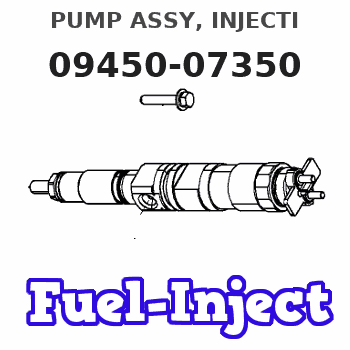
Information pump assy, injecti
Nozzle:
0935003840
Rating:
Components :
| 001. | PUMP ASSY, INJECTI | 09450-07350 |
Scheme ###:
| 000. | [01] | 09450-07350 | PUMP ASSY, INJECTI | 31B6502090 |
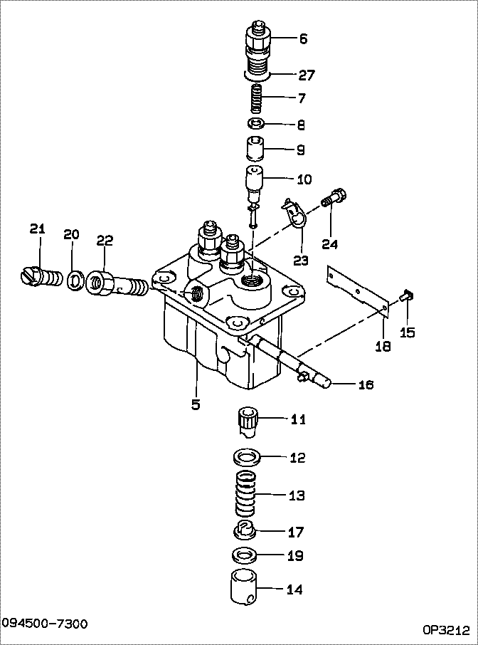
| 005. | [01] | 09011-05110 | HOUSING SUB-ASSY, | 47X0106100 |
| 006. | [03] | 09013-10520 | HOLDER, DELIVERY V | |
| 007. | [03] | 09013-60540 | SPRING, DELIVERY V | |
| 008. | [03] | 09013-70130 | GASKET, DELIVERY V | |
| 009. | [03] | 09014-02670 | VALVE SUB-ASSY, IN | 47X0111800 |
| 010. | [03] | 09015-05550 | ELEMENT SUB-ASSY, | 47X0105400 |
| 011. | [03] | 09016-10210 | SLEEVE, PLUNGER CO | |
| 012. | [03] | 09016-30082 | SEAT, SPRING, UPR | MM501098 |
| 013. | [03] | 09016-40170 | SPRING, PUMP PLUNG | |
| 014. | [03] | 09017-00170 | TAPPET SUB-ASSY,IN | EZ01775027 |
| 014-001. | [03] | 09017-10022 | TAPPET, INJECTION | |
| 014-002. | [03] | 09217-60010 | ROLLER, FEED PUMP | 09217-60010 |
| 014-003. | [03] | 09017-60020 | PIN, INJECTION PUM | |
| 015. | [03] | 09018-30050 | PIN, INJECTION PUM | |
| 016. | [01] | 09021-00470 | RACK ASSY, CONTROL | |
| 017. | [03] | 09030-10060 | SEAT, SPRING, LWR | EZ0177514 |
| 018. | [01] | 09046-70040 | PLATE | |
| 019. | [3C] | 09031-10010 | PLATE, TAPPET ADJU | 09031-10010 |
| 019. | [3C] | 09031-10310 | PLATE, TAPPET ADJU | |
| 019. | [3C] | 09031-10300 | PLATE, TAPPET ADJU | |
| 019. | [3C] | 09031-10280 | PLATE, TAPPET ADJU | |
| 019. | [3C] | 09031-10170 | PLATE, TAPPET ADJU | FR51530028 |
| 019. | [3C] | 09031-10160 | PLATE, TAPPET ADJU | FR51530027 |
| 019. | [3C] | 09031-10140 | PLATE, TAPPET ADJU | 09031-10140 |
| 019. | [3C] | 09031-10130 | PLATE, TAPPET ADJU | 09031-10130 |
| 019. | [3C] | 09031-10120 | PLATE, TAPPET ADJU | 09031-10120 |
| 019. | [3C] | 09031-10110 | PLATE, TAPPET ADJU | 09031-10110 |
| 020. | [01] | 94901-81020 | WASHER, COPPER PLA | 94901-81020 |
| 021. | [01] | 09024-40180 | SCREW, AIR BLEEDER | |
| 022. | [01] | 09024-50210 | SCREW, HOLLOW | |
| 023. | [02] | 09006-80020 | PLATE, ADJUSTING | |
| 024. | [02] | 94904-80800 | BOLT, WASHER HEAD | MM514195 |
| 027. | [03] | 90802-20150 | O-RING | |
| 027. | [03] | 09013-90410 | O-RING | 47X0122700 |
Include in #3:
09450-07350
as PUMP ASSY, INJECTI
Cross reference number
| Part num | Firm num | Firm | Name |
| 09450-07350 | 31B6502090 | PUMP ASSY, INJECTI | |
| 31B6502090 | MITSUBISHI | PUMP ASSY, INJECTI |
Information:
1. Remove shaft (2). Remove pin (1) from the shaft.2. Remove pins (3) from the flyweights. Remove flyweights (4). 3. Remove ring, races (6) and the bearing from riser (follower) (5). 4. Remove cover (7) and spring (8) from the governor housing. There is force on the cover from the spring.5. Remove seal (9) from the cover. 6. Remove cover (10) for the low and high idle adjustments.7. Remove locknut and screw (13) for the high idle adjustment.8. Remove bolt (15) and the washers for the low idle adjustment.9. Remove spring (16) and the guide.10. Remove pin (14) and plate (11).11. Remove shaft (12) from the housing. 12. Remove two spacers (17) and pin (18) from the shaft. 13. Remove shaft (19) from the governor housing.14. Remove washer (20) and levers (21) and (22) from the governor housing. 15. Remove seal (23) and the bearing.16. Remove seals (24) and (25) from the governor housing.Assemble Governor
1. Install the bearing and seal in the housing with tool (A). The lip of the seal must be toward the bearing. 2. Install seal (1) in housing with tool (A). The lip of the seal must be toward inside of housing.3. Install seal (2) in the housing with tool (B). The lip of the seal must be toward the inside of the housing. 4. Install shaft (3) in the housing. 5. Install plates (4), spacers (8) and pin (7) on shaft (5).6. Install shaft (5) in the housing and through washer (9) and levers (6). 7. Install pin (11) in the holes of the plates.8. Install screw (10) and the locknut for the high idle adjustment.9. Install spring (13) and the guide.10. Install bolt (12) and the washer for the low idle adjustment.11. Push plate and pin (11) over toward bolt (12) and tighten the bolt. 12. Install the seal in cover (14) with tooling (B). The lip of the seal must be toward the inside. 13. Install spring (15) in the cover. Install cover (14) on the housing.
Spring (15) must be installed with the end of the spring in the position shown.
14. Install the cover (16) for the idle adjustment screws. 15. Install bearing (19) between races (18) on riser (follower) (17). Install ring (20). Ring (20) holds the washers on the riser (follower).16. Install the pin in shaft (23). 17. Install flyweights (22) and pin (21).18. Install shaft (23) in the flyweight assembly.end by: a) connection of governor to fuel injection pump housingb) Make adjustment of fuel system setting (See Fuel System Setting in Testing and Adjusting.)