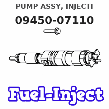
Information pump assy, injecti
Nozzle:
0935003840
Rating:
Components :
| 001. | PUMP ASSY, INJECTI | 09450-07110 |
Scheme ###:
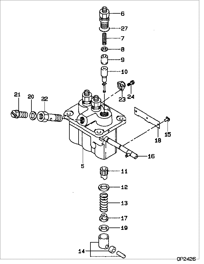
| 000. | [01] | 09450-07110 | PUMP ASSY, INJECTI | 31B6502080 |
| 005. | [01] | 09011-05110 | HOUSING SUB-ASSY, | 47X0106100 |
| 006. | [03] | 09013-10520 | HOLDER, DELIVERY V | |
| 007. | [03] | 09013-60540 | SPRING, DELIVERY V | |
| 008. | [03] | 09013-70130 | GASKET, DELIVERY V | |
| 009. | [03] | 09014-02610 | VALVE SUB-ASSY, IN | 47X0107700 |
| 010. | [03] | 09015-05550 | ELEMENT SUB-ASSY, | 47X0105400 |
| 011. | [03] | 09016-10210 | SLEEVE, PLUNGER CO | |
| 012. | [03] | 09016-30082 | SEAT, SPRING, UPR | MM501098 |
| 013. | [03] | 09016-40170 | SPRING, PUMP PLUNG | |
| 014. | [03] | 09017-00170 | TAPPET SUB-ASSY,IN | EZ01775027 |
| 015. | [03] | 09018-30050 | PIN, INJECTION PUM | |
| 016. | [01] | 09021-00470 | RACK ASSY, CONTROL | |
| 017. | [03] | 09030-10060 | SEAT, SPRING, LWR | EZ0177514 |
| 018. | [01] | 09046-70040 | PLATE | |
| 019. | [3C] | 09031-10310 | PLATE, TAPPET ADJU | |
| 019. | [3C] | 09031-10300 | PLATE, TAPPET ADJU | |
| 019. | [3C] | 09031-10280 | PLATE, TAPPET ADJU | |
| 019. | [3C] | 09031-10170 | PLATE, TAPPET ADJU | FR51530028 |
| 019. | [3C] | 09031-10160 | PLATE, TAPPET ADJU | FR51530027 |
| 019. | [3C] | 09031-10140 | PLATE, TAPPET ADJU | 09031-10140 |
| 019. | [3C] | 09031-10130 | PLATE, TAPPET ADJU | 09031-10130 |
| 019. | [3C] | 09031-10120 | PLATE, TAPPET ADJU | 09031-10120 |
| 019. | [3C] | 09031-10110 | PLATE, TAPPET ADJU | 09031-10110 |
| 019. | [3C] | 09031-10010 | PLATE, TAPPET ADJU | 09031-10010 |
| 020. | [01] | 94901-81020 | WASHER, COPPER PLA | 94901-81020 |
| 020. | [01] | 09022-20080 | WASHER, FUEL PIPE | MM500114 |
| 021. | [01] | 09024-40180 | SCREW, AIR BLEEDER | MM501152 |
| 022. | [01] | 09024-50210 | SCREW, HOLLOW | |
| 023. | [02] | 09006-80020 | PLATE, ADJUSTING | |
| 024. | [02] | 94904-80800 | BOLT, WASHER HEAD | MM514195 |
| 027. | [03] | 90802-20150 | O-RING | |
| 027. | [03] | 09013-90410 | O-RING | 47X0122700 |
Include in #3:
09450-07110
as PUMP ASSY, INJECTI
Cross reference number
| Part num | Firm num | Firm | Name |
| 09450-07110 | 31B6502080 | PUMP ASSY, INJECTI | |
| 31B6502080 | MITSUBISHI | PUMP ASSY, INJECTI |
Information:
1. Check each bearing cap (1) for its location on the engine. Each cap has an arrow which is toward the front of the block and a number which gives the location of that cap. Keep each bearing with the correct cap. 2. Remove bearing caps No. 2 through No. 4. Remove thrust plates from No. 3 upper bearing.3. Install one of the flywheel bolts in each end of the crankshaft. Fasten a hoist to the crankshaft as shown. Remove No. 1 and No. 5 main bearing caps. Remove the crankshaft. Weight of the crankshaft is 270 lb. (122 kg).
Be careful not to cause damage to the crankshaft journals when the crankshaft is removed.
4. Remove crankshaft gear (2) with tooling (A).5. Remove dowel and pin from crankshaft with tooling (B).Install Crankshaft
1. Install pin (1) in the crankshaft end until it is extended from the surface .25 .02 in. (6.4 0.5 mm).2. Install dowel (2) until it is extended from the surface .16 .02 in. (4.1 0.5 mm). 3. Heat crankshaft gear (3) to a maximum temperature of 400°F (204°C). Install gear (3) on the crankshaft with groove (4) in alignment with dowel (2).4. Make sure the upper main bearings are clean. Put clean oil on the upper main bearings and journals of the crankshaft.5. Install one of the flywheel bolts in each end of the crankshaft. Fasten a hoist to the crankshaft and put it in position in the block.
Do not cause damage to the crankshaft journals. Make sure the "V" mark on the crankshaft gear is in alignment with the "V" mark on the idler gear.
For more detail about installation of main bearings see REMOVE AND INSTALL CRANKSHAFT MAIN BEARINGS.6. Check the bearing clearances with tool (B).7. Put clean engine oil on the bolts for caps No. 1 and No. 5. Install No. 1 and No. 5 caps with the bolts finger tight. Make sure the arrows on the caps are toward the front of the block. 8. Install thrust plates (5) for the No. 3 upper main bearing. Install the thrust plates with the side that has the identification "Block Side" toward the cylinder block.9. Put clean oil on the bolts for caps No. 2 through No. 4. Install caps No. 2 through No. 4 with the bolts finger tight. Make sure the arrows are toward the front of the block.10. Tighten the cap bolts as follows: a) Tighten the bolts on the tab end of the caps first to a torque of 190 10 lb. ft. (260 14 N m).b) Tighten the bolts on the other end of the caps to a torque of 190 10 lb. ft. (260 14 N m).c) Put a mark across the bolt head and cap. Tighten the bolts opposite the tab end 120°. Tighten the bolts on the tab end of the cap 120°. 11. Check the end play of the crankshaft with tool (A). Make sure the dial indicator is