Information pump assy, injecti
Nozzle:
0935003840
Rating:
Components :
| 001. | PUMP ASSY, INJECTI | 09450-07100 |
Scheme ###:
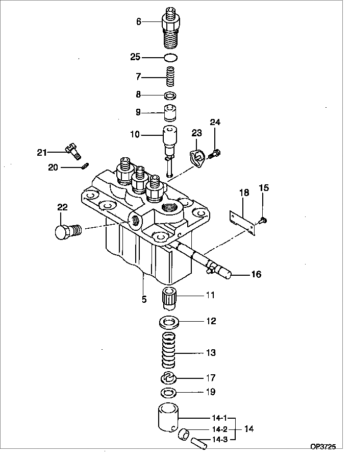
| 000. | [01] | 09450-07100 | PUMP ASSY, INJECTI | 31A6502070 |
| 005. | [01] | 09011-05070 | HOUSING SUB-ASSY, | 47X0104200 |
| 006. | [04] | 09013-10520 | HOLDER, DELIVERY V | |
| 007. | [04] | 09013-60540 | SPRING, DELIVERY V | |
| 008. | [04] | 09013-70130 | GASKET, DELIVERY V | |
| 009. | [04] | 09014-02670 | VALVE SUB-ASSY, IN | 47X0111800 |
| 010. | [04] | 09015-05550 | ELEMENT SUB-ASSY, | 47X0105400 |
| 011. | [04] | 09016-10210 | SLEEVE, PLUNGER CO | |
| 012. | [04] | 09016-30082 | SEAT, SPRING, UPR | MM501098 |
| 013. | [04] | 09016-40170 | SPRING, PUMP PLUNG | |
| 014. | [04] | 09017-00170 | TAPPET SUB-ASSY,IN | EZ01775027 |
| 014-001. | [04] | 09017-10022 | TAPPET, INJECTION | |
| 014-002. | [04] | 09217-60010 | ROLLER, FEED PUMP | 09217-60010 |
| 014-003. | [04] | 09017-60020 | PIN, INJECTION PUM | |
| 015. | [04] | 09018-30050 | PIN, INJECTION PUM | |
| 016. | [01] | 09021-00440 | RACK ASSY, CONTROL | |
| 017. | [04] | 09030-10060 | SEAT, SPRING, LWR | EZ0177514 |
| 018. | [02] | 09046-70030 | PLATE | |
| 019. | [4C] | 09031-10010 | PLATE, TAPPET ADJU | 09031-10010 |
| 019. | [4C] | 09031-10310 | PLATE, TAPPET ADJU | |
| 019. | [4C] | 09031-10300 | PLATE, TAPPET ADJU | |
| 019. | [4C] | 09031-10280 | PLATE, TAPPET ADJU | |
| 019. | [4C] | 09031-10170 | PLATE, TAPPET ADJU | FR51530028 |
| 019. | [4C] | 09031-10160 | PLATE, TAPPET ADJU | FR51530027 |
| 019. | [4C] | 09031-10140 | PLATE, TAPPET ADJU | 09031-10140 |
| 019. | [4C] | 09031-10130 | PLATE, TAPPET ADJU | 09031-10130 |
| 019. | [4C] | 09031-10120 | PLATE, TAPPET ADJU | 09031-10120 |
| 019. | [4C] | 09031-10110 | PLATE, TAPPET ADJU | 09031-10110 |
| 020. | [01] | 94901-81020 | WASHER, COPPER PLA | 94901-81020 |
| 021. | [01] | 09024-40180 | SCREW, AIR BLEEDER | |
| 022. | [01] | 94918-00310 | SCREW, HOLLOW | 85265-00078 |
| 023. | [03] | 09006-80020 | PLATE, ADJUSTING | |
| 024. | [03] | 94904-80800 | BOLT, WASHER HEAD | MM514195 |
| 025. | [04] | 90802-20150 | O-RING | |
| 025. | [04] | 09013-90410 | O-RING | 47X0122700 |
Include in #3:
09450-07100
as PUMP ASSY, INJECTI
Cross reference number
| Part num | Firm num | Firm | Name |
| 09450-07100 | 31A6502070 | PUMP ASSY, INJECTI | |
| 31A6502070 | MITSUBISHI | PUMP ASSY, INJECTI |
Information:
start by:a) remove oil pump 1. Check each main bearing cap (2) for its location on the engine. Each cap has an arrow (1) to show the front of the block and a number (3) which gives the location of that cap.2. Remove No. 2 through No. 4 main bearing caps from the engine. Remove the lower bearings from the caps.3. Remove the thrust plate from each side of the No. 3 upper main bearing. 4. Turn the crankshaft until tool (A) can be installed in oil hole (4). Turn the crankshaft in the direction which will push the upper main bearing out, tab end first.
If the crankshaft is turned in the wrong direction, the tab of the bearing will be pushed between the crankshaft and the cylinder block. This will cause damage to the crankshaft and block.
5. Install lower bearings in the bearing caps.6. Install upper bearing in the cylinder block with tool (A). Be sure tab (5) on the back of the bearings fits in the groove of the caps and cylinder block.
When bearing caps are installed, make sure the caps are installed with the part number toward the front of the engine and the number on the bottom of the cap is the same as the number on the camshaft side of the engine.
When the bearing clearance is checked and the engine is in a vertical position, such as in the vehicle, the crankshaft will have to be lifted up and held against the upper halves of the main bearings to get a correct measurement with Plastigage (B). The Plastigage will not hold the weight of the crankshaft and give a correct indication. If the engine is in a horizontal position, such as on an engine stand, it is not necessary to hold the crankshaft up. Do not turn crankshaft when Plastigage is in position to check clearance.7. Check the bearing clearance with tool (B) as follows: a) Put tool (B) in position as shown.b) Put clean oil on the threads of the cap bolts. Install the caps and cap bolts, finger tight.c) Tighten the bolts on the tab end of the caps first to a torque of 190 10 lb.ft. (260 14 N m).d) Tighten the bolts on the other end of the caps to a torque of 190 10 lb.ft. (260 14 N m). e) Put a mark across the bolt head and cap. Tighten the bolts opposite the tab end 120°. Tighten the bolts on the tab end of the cap 120° more. Make sure the main bearing caps are installed with their identification number (7) in alignment with the identification number on the left side of the cylinder block and arrow (6) toward the front of the block.8. Remove the main bearing caps and tool (B).9. Measure the width of the Plastigage to determine the bearing clearance. The clearance for new bearings must be .0036 to .0073 in. (0.091 to 0.186 mm). The maximum clearance for used