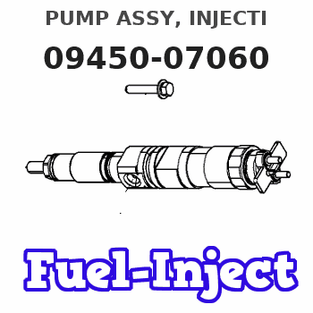
Information pump assy, injecti
Nozzle:
0935006790
Rating:
Compare Prices: .
As an associate, we earn commssions on qualifying purchases through the links below

IMELBUFF 1C010-51010 094500-7060 Fuel Injection Pump for Kubota V3300 V3600 V3800 V3300TE Engine M6800 M6800DH M8200 M8200DH M9000 M Series Tractors
IMELBUFF 🚜Part Number: 1C010-51010 1C01051010 094500-7060 || 🚜Engine Model: for Kubota Engine V3300 V3600 V3800 V3300TE V3600TE || 🚜Vehicle Application: for Kubota M Series Tractors M6800DH M6800DHC M6800DT M6800SDT M6800S-CAB M6800SDT-CAB M8200DCN M8200DH M8200DHC M8200DT M8200DT-CAB M8200DTN M8200SDTN M9000DT M9000DTM M9000DTMC ME9000DH ME8200DHC ME9000DHC || 🚜Warm Tips: Please check your part numbers before placing an order. If you are not sure, you can send us your engine model or fuel pump part number || 🚜Service: 5-months warranty and 24 hour support for customer service. Please feel free to contact us by email if you have any question with the product
IMELBUFF 🚜Part Number: 1C010-51010 1C01051010 094500-7060 || 🚜Engine Model: for Kubota Engine V3300 V3600 V3800 V3300TE V3600TE || 🚜Vehicle Application: for Kubota M Series Tractors M6800DH M6800DHC M6800DT M6800SDT M6800S-CAB M6800SDT-CAB M8200DCN M8200DH M8200DHC M8200DT M8200DT-CAB M8200DTN M8200SDTN M9000DT M9000DTM M9000DTMC ME9000DH ME8200DHC ME9000DHC || 🚜Warm Tips: Please check your part numbers before placing an order. If you are not sure, you can send us your engine model or fuel pump part number || 🚜Service: 5-months warranty and 24 hour support for customer service. Please feel free to contact us by email if you have any question with the product
Components :
| 001. | PUMP ASSY, INJECTI | 09450-07060 |
Scheme ###:
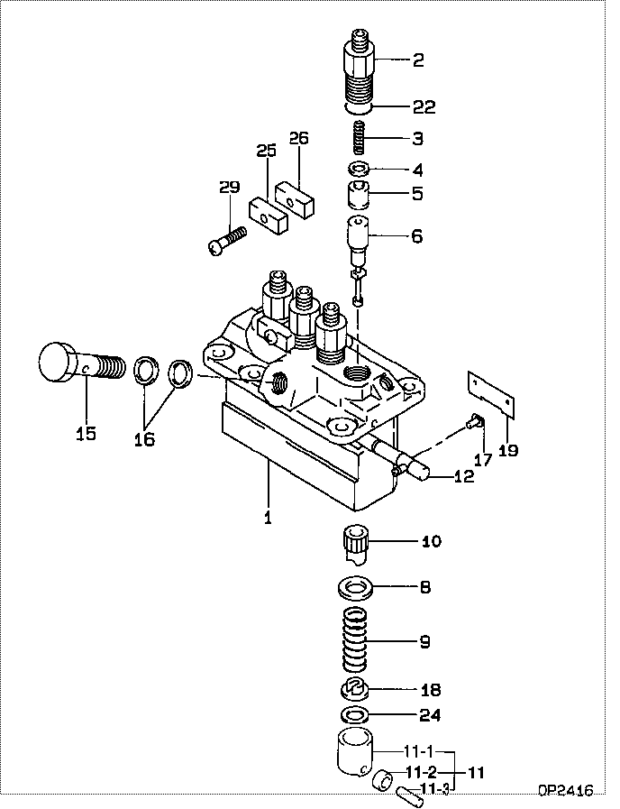
| 000. | [01] | 09450-07060 | PUMP ASSY, INJECTI | |
| 001. | [01] | 09011-05260 | HOUSING SUB-ASSY, | |
| 002. | [04] | 09013-00450 | HOLDER SUB-ASSY, D | 16415-51221 |
| 003. | [04] | 09013-61100 | SPRING, DELIVERY V | 16454-51231 |
| 004. | [04] | 09013-70130 | GASKET, DELIVERY V | 11420-51241 |
| 005. | [04] | 09014-00410 | VALVE SUB-ASSY, IN | 15221-51031 |
| 006. | [04] | 09015-05920 | ELEMENT SUB-ASSY, | |
| 008. | [04] | 09016-30082 | SEAT, SPRING, UPR | 15221-51271 |
| 009. | [04] | 09016-40170 | SPRING, PUMP PLUNG | 15221-51281 |
| 010. | [04] | 09016-10210 | SLEEVE, PLUNGER CO | 15221-51382 |
| 011. | [04] | 09017-00170 | TAPPET SUB-ASSY,IN | 15221-51071 |
| 011-001. | [04] | 09017-10022 | TAPPET, INJECTION | 15021-51990 |
| 011-002. | [04] | 09217-60010 | ROLLER, FEED PUMP | 15109-52931 |
| 011-003. | [04] | 09017-60020 | PIN, INJECTION PUM | 15021-51970 |
| 012. | [01] | 09021-00820 | RACK ASSY, CONTROL | |
| 015. | [01] | 94918-00310 | SCREW, HOLLOW | 15101-51321 |
| 016. | [02] | 09022-20050 | WASHER, FUEL PIPE | 15109-51731 |
| 017. | [04] | 09018-30050 | PIN, INJECTION PUM | 14611-51251 |
| 018. | [04] | 09030-10060 | SEAT, SPRING, LWR | 15021-51291 |
| 019. | [02] | 09046-70030 | PLATE | 14611-51441 |
| 022. | [04] | 90802-20150 | O-RING | 14611-51201 |
| 022. | [04] | 09013-90410 | O-RING | |
| 024. | [4C] | 09031-10310 | PLATE, TAPPET ADJU | |
| 024. | [4C] | 09031-10300 | PLATE, TAPPET ADJU | |
| 024. | [4C] | 09031-10280 | PLATE, TAPPET ADJU | |
| 024. | [4C] | 09031-10170 | PLATE, TAPPET ADJU | |
| 024. | [4C] | 09031-10160 | PLATE, TAPPET ADJU | |
| 024. | [4C] | 09031-10140 | PLATE, TAPPET ADJU | |
| 024. | [4C] | 09031-10130 | PLATE, TAPPET ADJU | 15221-51491 |
| 024. | [4C] | 09031-10120 | PLATE, TAPPET ADJU | |
| 024. | [4C] | 09031-10110 | PLATE, TAPPET ADJU | |
| 024. | [4C] | 09031-10010 | PLATE, TAPPET ADJU | 14109-51301 |
| 025. | [02] | 09023-10081 | PLATE, DELIVERY VA | |
| 026. | [02] | 09023-20050 | PLATE, DELIVERY VA | |
| 029. | [02] | 94904-44330 | BOLT |
Include in #3:
09450-07060
as PUMP ASSY, INJECTI
Cross reference number
| Part num | Firm num | Firm | Name |
| 09450-07060 | PUMP ASSY, INJECTI |
Information:
1. Remove five bolts (1) that hold oil lines bracket and supports to the engine.2. Remove three bolts (2) that hold oil pump to the engine.3. Remove the oil pump with the lines as a unit from under the engine. 4. Remove oil lines (3) from the oil pump.Install Oil Pump (Brakesaver)
1. Put clean SAE 30 engine oil on the O-ring seals. Connect the oil lines in the oil pump. Install the bolt and washer that holds the line in the pump.2. Put the oil pump and the oil lines as a unit in position under the engine.3. Install the three bolts that hold the pump to the engine. Make sure the oil pump gear is engaged with crankshaft gear.4. Install the five bolts that hold the oil lines bracket and support to the engine.end by:a) install oil panDisassemble Oil Pump (Brakesaver)
start by:a) remove oil pump1. Remove bolt and washer that hold gear on the shaft. 2. Use tooling (A) to remove drive gear (1) from shaft. Remove the key from shaft. Put marks on the pump bodies so they can be assembled in the correct position.3. Remove retainer (3) for bypass valve. Remove spring and bypass valve. 4. Remove bolts (4) that hold pump body (2) to the main pump body. Remove the pump body (2).5. Use tooling (B) to remove the bearings from pump body (2). 6. Remove the gears (7). Put marks on the gears so they can be assembled in the same position.7. Remove the spacer (6) from the main oil pump body (5). Use tooling (C) to remove the bearings from spacer (6).8. Remove the gears from main pump body (5). 9. Use tooling (C) to remove the bearings from the main pump body.Assemble Oil Pump (Brakesaver)
1. Use tooling (A) to install the bearings (2) until they are even with the outside surface of the main pump body (1). Install the bearings (2) so the junctions in the bearings are 30° 15° from the center of the bearing bores and toward the oil pump outlet passage as shown. 2. Use tooling (A) to install the bearings (3) in the spacer. Install the bearings until they are in position an equal distance in from each side of the spacer. Install the bearings with the oil holes in the bearings in alignment with the oil holes in the spacer and the junctions in the bearings in alignment with the cavity in the spacer as shown. 3. Put clean engine oil on all gears and bearings before they are assembled in the oil pump. Install the idler and drive gears (5) in the main pump body.4. Install the spacer (4) on the gear shafts with the smaller cavity out and the oil holes in the spacer toward the pump outlet passage as shown. 5. Use tooling (B) to install the bearings (6) in the pump body (7) until they are .060 .010 in. (1.52 0.25 mm) from the inside edge of the bearing