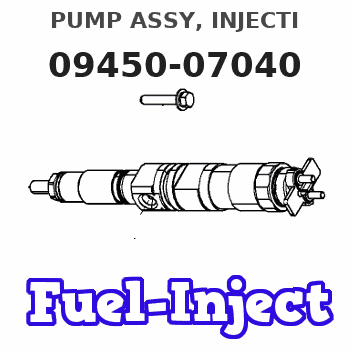
Information pump assy, injecti
Nozzle:
0935003840
Rating:
Compare Prices: .
As an associate, we earn commssions on qualifying purchases through the links below

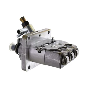
094500-7040 094500-5160 30L65-01700 MM436649 EJ7413168 Fuel Injection Pump Suitable for Mitsubishi L3E Engine MHI Doosan Solar 015PLUS S018-VT
OfkZynodor Part Name: Fuel Injection Pump || Part Number:094500-7040 094500-5160 30L65-01700 MM436649 EJ7413168 || Application:Suitable for Mitsubishi L3E Engine MHI Doosan Solar 015PLUS S018-VT || Please make sure to carefully compare the photos and check the part numbers before making the purchase. If you are unable to confirm your engine model or part number, please leave us a message and we will assist you in confirming that the product you purchase is the one you need. || Your order is not merely a single purchase but the beginning of a cooperative journey, aiming to ensure the safe and smooth operation of your vehicle. We are proud to offer you reliable precision engineering components and unparalleled services.
OfkZynodor Part Name: Fuel Injection Pump || Part Number:094500-7040 094500-5160 30L65-01700 MM436649 EJ7413168 || Application:Suitable for Mitsubishi L3E Engine MHI Doosan Solar 015PLUS S018-VT || Please make sure to carefully compare the photos and check the part numbers before making the purchase. If you are unable to confirm your engine model or part number, please leave us a message and we will assist you in confirming that the product you purchase is the one you need. || Your order is not merely a single purchase but the beginning of a cooperative journey, aiming to ensure the safe and smooth operation of your vehicle. We are proud to offer you reliable precision engineering components and unparalleled services.

Compatible with Mitsubishi Engine L3E Fuel Injection Pump 094500-5160 094500-7040 MM436649
KoovDem Part Number: 094500-5160 094500-7040 MM436649 Note: Please check the fitment carefully before purchase. Or just tell us the part number you need. || Part Name: Fuel Injection Pump || The compact and efficient L3E engine is known for its reliability, performance, and superior fuel efficiency. It is lightweight and ideal for various applications, from small construction equipment to generators. With advanced technology and robust construction, the L3E engine ensures long-lasting durability and high performance in challenging environments. Its compact size and ease of installation make it a popular choice for a wide range of industries seeking a dependable power source. || Suitable for use with Mitsubishi Engine L3E || Package includes: 1 piece of Fuel Injection Pump with part numbers 094500-5160 and 094500-7040, as well as MM436649.
KoovDem Part Number: 094500-5160 094500-7040 MM436649 Note: Please check the fitment carefully before purchase. Or just tell us the part number you need. || Part Name: Fuel Injection Pump || The compact and efficient L3E engine is known for its reliability, performance, and superior fuel efficiency. It is lightweight and ideal for various applications, from small construction equipment to generators. With advanced technology and robust construction, the L3E engine ensures long-lasting durability and high performance in challenging environments. Its compact size and ease of installation make it a popular choice for a wide range of industries seeking a dependable power source. || Suitable for use with Mitsubishi Engine L3E || Package includes: 1 piece of Fuel Injection Pump with part numbers 094500-5160 and 094500-7040, as well as MM436649.

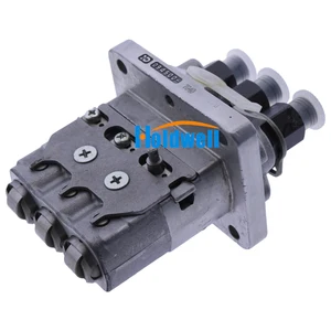
VIIKEND Fuel Injection Pump 30L65-01700 094500-7040 094500-5160 Compatible with Mitsubishi Engine L3E
VIIKEND Part Name: Fuel Injection Pump || Part Number: 30L65-01700 094500-7040 Note: Please check the fitment carefully before purchase. Or just tell us the part number you need. || Engine Model: L3E || Applicable: Compatible with Mitsubishi Engine L3E || Package included: 1pcs Fuel Injection Pump 30L65-01700 094500-7040 094500-5160
VIIKEND Part Name: Fuel Injection Pump || Part Number: 30L65-01700 094500-7040 Note: Please check the fitment carefully before purchase. Or just tell us the part number you need. || Engine Model: L3E || Applicable: Compatible with Mitsubishi Engine L3E || Package included: 1pcs Fuel Injection Pump 30L65-01700 094500-7040 094500-5160
You can express buy:
USD 922.54
19-05-2025
19-05-2025
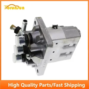
For Mitsubishi L3E Engine Fuel Pump 094500-5160 094500-7040 MM436649
USD 825.89
13-05-2025
13-05-2025
Holdwell Fuel Injection Pump 30L65-01700 30L6501700 MM436649 094500-7040 0945007040 for Mitsubishi Engine L3E
USD 868
27-04-2025
27-04-2025
Fuel Injection Pump 094500-5160 094500-7040 MM436649 for Mitsubishi L3E Engine
Components :
| 001. | PUMP ASSY, INJECTI | 09450-07040 |
Scheme ###:
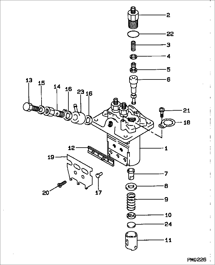
| 000. | [01] | 09450-07040 | PUMP ASSY, INJECTI | |
| 001. | [01] | 09011-03730 | HOUSING SUB-ASSY, | |
| 002. | [03] | 09013-10830 | HOLDER, DELIVERY V | MM501918 |
| 003. | [03] | 09013-60530 | SPRING, DELIVERY V | |
| 004. | [03] | 09013-70130 | GASKET, DELIVERY V | |
| 005. | [03] | 09014-02110 | VALVE SUB-ASSY, IN | |
| 006. | [03] | 09015-04280 | ELEMENT SUB-ASSY, | |
| 007. | [03] | 09016-00140 | SLEEVE SUB-ASSY, C | |
| 008. | [03] | 09016-30140 | SEAT, SPRING, UPR | |
| 009. | [03] | 09016-40220 | SPRING, PUMP PLUNG | MM501926 |
| 010. | [03] | 09016-50170 | SEAT, SPRING, LWR | |
| 011. | [03] | 09017-00220 | TAPPET SUB-ASSY,IN | |
| 012. | [01] | 09021-00560 | RACK ASSY, CONTROL | |
| 013. | [01] | 09024-40010 | SCREW, AIR BLEEDER | 09024-40010 |
| 014. | [01] | 09024-50310 | SCREW, HOLLOW | |
| 015. | [01] | 09024-80010 | WASHER, DRAIN SCRE | 09024-80010 |
| 016. | [02] | 09025-10010 | WASHER, INJECTION | 85265-00077 |
| 017. | [03] | 09018-30090 | PIN, INJECTION PUM | |
| 018. | [03] | 09023-00070 | PLATE SET, VALVE H | |
| 019. | [01] | 09069-11020 | BRACKET, STOP WIRE | |
| 020. | [02] | 94900-20500 | SCREW, COUNTERSUNK | |
| 021. | [03] | 94900-75390 | SCREW, W/WASHER | |
| 022. | [03] | 90801-10130 | O-RING | |
| 022. | [03] | 09013-90400 | O-RING | |
| 023. | [01] | 09221-70590 | NIPPLE, SWIVEL | |
| 024. | [3C] | 09031-10400 | PLATE, TAPPET ADJU | |
| 024. | [3C] | 09031-10410 | PLATE, TAPPET ADJU | |
| 024. | [3C] | 09031-10420 | PLATE, TAPPET ADJU | |
| 024. | [3C] | 09031-10430 | PLATE, TAPPET ADJU | |
| 024. | [3C] | 09031-10440 | PLATE, TAPPET ADJU | |
| 024. | [3C] | 09031-10390 | PLATE, TAPPET ADJU | |
| 024. | [3C] | 09031-10380 | PLATE, TAPPET ADJU | |
| 024. | [3C] | 09031-10370 | PLATE, TAPPET ADJU | |
| 024. | [3C] | 09031-10360 | PLATE, TAPPET ADJU | |
| 024. | [3C] | 09031-10350 | PLATE, TAPPET ADJU | |
| 024. | [3C] | 09031-10340 | PLATE, TAPPET ADJU | |
| 024. | [3C] | 09031-10330 | PLATE, TAPPET ADJU | |
| 024. | [3C] | 09031-10320 | PLATE, TAPPET ADJU | |
| 024. | [3C] | 09031-10450 | PLATE, TAPPET ADJU |
Include in #3:
09450-07040
as PUMP ASSY, INJECTI
Cross reference number
| Part num | Firm num | Firm | Name |
| 09450-07040 | PUMP ASSY, INJECTI |
Information:
2. Remove oil filter base support (2), air line (3) and oil level gauge tube (4). Remove the right lifting eye (1) and the left lifting eye. 3. Remove glow plug leads (5) and the 3/8 in. bolts from the cylinder head. Glow plug leads are on the precombustion engine only.4. Install two 5/16"-18 NC forged eyebolts and nuts in the cylinder head. Fasten a hoist to the cylinder head.5. Remove cylinder head bolts (6) and the washers. Clean all debris or foreign material from the "V" of the engine before removal of the cylinder head.6. Remove the cylinder head. Weight of the cylinder head is 200 lb. (90 kg). Put a cover over the intake manifold portion of the cylinder head to keep dirt and foreign material out.
Do not put the cylinder head down on a flat surface. This can cause damage to the fuel injection valves.
A new spacer plate gasket must be installed when the cylinder head is removed. See REMOVE AND INSTALL SPACER PLATE.Install Cylinder Head
1. Clean the spacer plate and the bottom surface of the cylinder head. Put a new cylinder head gasket (3) and seals (4) in position on the spacer plate as shown.2. Fasten a hoist to cylinder head (2) and put it in position over dowels (5) in the cylinder block.3. Put clean SAE 30 oil on the threads of the bolts that hold the cylinder head in position. Install the bolts and washers and tighten them to the correct torque as follows: a) Tighten bolts 1 through 14 in number sequence to a torque of 200 20 lb.ft. (270 25 N m).b) Tighten bolts 1 through 14 in number sequence to a torque of 330 15 lb.ft. (447 20 N m).c) Tighten bolts 1 through 14 again in number sequence to a torque of 330 15 lb.ft. (447 20 N m).d) Install the rocker shaft assembly and push rods.e) Tighten bolts 15 through 18 in number sequence to a torque of 200 20 lb.ft. (270 25 N m).f) Tighten bolts 15 through 18 in number sequence to a torque of 330 15 lb.ft. (447 20 N m).g) Tighten bolts 15 through 18 again in number sequence to a torque of 330 15 lb.ft. (447 20 N m).4. Install the glow plug leads and the 3/8 in. bolts in the cylinder head. Tighten the bolts to a torque of 32 5 lb.ft. (43 7 N m). If studs (1) were removed, install new studs and tighten them to a torque of 20 3 lb.ft. (25 4 N m).5. Make an adjustment for the valve clearance. The clearance must be .015 .003 in. (0.38 0.07 mm) for intake and .030 .003 in. (0.76 0.07 mm) for exhaust. See VALVE CLEARANCE SETTING in TESTING AND ADJUSTING.6. Install the left and right lifting eyes.7. Install the oil level gauge tube, air line and oil