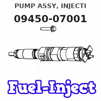
Information pump assy, injecti
Rating:
Components :
| 001. | PUMP ASSY, INJECTI | 09450-07001 |
Scheme ###:

| 000. | [01] | 09450-07001 | PUMP ASSY, INJECTI | 30A6514600 |
| 005. | [01] | 09011-02420 | HOUSING SUB-ASSY, | MM501253 |
| 006. | [04] | 09013-10720 | HOLDER, DELIVERY V | |
| 007. | [04] | 09013-60480 | SPRING, DELIVERY V | |
| 008. | [04] | 09013-70130 | GASKET, DELIVERY V | |
| 009. | [04] | 09014-02520 | VALVE SUB-ASSY, IN | 47X0105000 |
| 010. | [04] | 09015-04640 | ELEMENT SUB-ASSY, | |
| 011. | [04] | 09016-10210 | SLEEVE, PLUNGER CO | |
| 012. | [04] | 09016-30082 | SEAT, SPRING, UPR | MM501098 |
| 013. | [04] | 09016-40170 | SPRING, PUMP PLUNG | |
| 014. | [04] | 09017-00170 | TAPPET SUB-ASSY,IN | EZ01775027 |
| 014-001. | [04] | 09017-10022 | TAPPET, INJECTION | |
| 014-002. | [04] | 09217-60010 | ROLLER, FEED PUMP | 09217-60010 |
| 014-003. | [04] | 09017-60020 | PIN, INJECTION PUM | |
| 015. | [04] | 09018-30050 | PIN, INJECTION PUM | |
| 016. | [01] | 09021-00440 | RACK ASSY, CONTROL | |
| 017. | [04] | 09030-10060 | SEAT, SPRING, LWR | EZ0177514 |
| 018. | [02] | 09046-70030 | PLATE | |
| 019. | [4C] | 09031-10310 | PLATE, TAPPET ADJU | |
| 019. | [4C] | 09031-10300 | PLATE, TAPPET ADJU | |
| 019. | [4C] | 09031-10280 | PLATE, TAPPET ADJU | |
| 019. | [4C] | 09031-10170 | PLATE, TAPPET ADJU | FR51530028 |
| 019. | [4C] | 09031-10160 | PLATE, TAPPET ADJU | FR51530027 |
| 019. | [4C] | 09031-10140 | PLATE, TAPPET ADJU | 09031-10140 |
| 019. | [4C] | 09031-10130 | PLATE, TAPPET ADJU | 09031-10130 |
| 019. | [4C] | 09031-10120 | PLATE, TAPPET ADJU | 09031-10120 |
| 019. | [4C] | 09031-10110 | PLATE, TAPPET ADJU | 09031-10110 |
| 019. | [4C] | 09031-10010 | PLATE, TAPPET ADJU | 09031-10010 |
| 020. | [01] | 94901-81020 | WASHER, COPPER PLA | 94901-81020 |
| 021. | [01] | 09314-10260 | NIPPLE, OIL LEAKAG | |
| 022. | [01] | 94918-00310 | SCREW, HOLLOW | 85265-00078 |
| 023. | [03] | 09006-80020 | PLATE, ADJUSTING | |
| 024. | [03] | 94904-80800 | BOLT, WASHER HEAD | MM514195 |
| 025. | [01] | 09055-40470 | SPRING, DIAPHRAGM | |
| 026. | [01] | 09055-40280 | SPRING, DIAPHRAGM | |
| 027. | [04] | 90802-20150 | O-RING | |
| 027. | [04] | 09013-90410 | O-RING | 47X0122700 |
| 028. | [01] | 09089-40020 | E-RING | MM501496 |
| 029. | [01] | 09089-40010 | E-RING | 09089-40010 |
| 032. | [1C] | 09021-95370 | STOPPER | |
| 032. | [1C] | 09021-95360 | STOPPER | MM501747 |
| 032. | [1C] | 09021-93120 | STOPPER | |
| 032. | [1C] | 09021-93110 | STOPPER | |
| 032. | [1C] | 09021-93100 | STOPPER | |
| 032. | [1C] | 09021-93090 | STOPPER | |
| 032. | [1C] | 09021-93080 | STOPPER | |
| 033. | [1C] | 09021-96980 | STOPPER | |
| 033. | [1C] | 09021-96990 | STOPPER | |
| 033. | [1C] | 09021-97000 | STOPPER | |
| 033. | [1C] | 09021-97010 | STOPPER | |
| 033. | [1C] | 09021-93990 | STOPPER | |
| 033. | [1C] | 09021-94000 | STOPPER | |
| 033. | [1C] | 09021-94010 | STOPPER | |
| 033. | [1C] | 09021-94020 | STOPPER | |
| 033. | [1C] | 09021-96970 | STOPPER | |
| 033. | [1C] | 09021-94130 | STOPPER | |
| 033. | [1C] | 09021-94120 | STOPPER | |
| 033. | [1C] | 09021-94040 | STOPPER | |
| 033. | [1C] | 09021-94050 | STOPPER | |
| 033. | [1C] | 09021-94060 | STOPPER | |
| 033. | [1C] | 09021-94070 | STOPPER | |
| 033. | [1C] | 09021-94080 | STOPPER | |
| 033. | [1C] | 09021-94090 | STOPPER | |
| 033. | [1C] | 09021-94100 | STOPPER | |
| 033. | [1C] | 09021-94110 | STOPPER | |
| 033. | [1C] | 09021-94030 | STOPPER |
Include in #3:
09450-07001
as PUMP ASSY, INJECTI
Cross reference number
| Part num | Firm num | Firm | Name |
| 09450-07001 | 30A6514600 | PUMP ASSY, INJECTI |
Information:
2. Remove two studs (1).3. Turn the engine with tool (A) to remove four bolts (2) from the rear balance weight gear.4. Turn the engine again with tool (A) until the "V" marks on all the timing gears are in alignment with each other.5. With the timing marks in alignment, install tooling (B) in the location of rear studs (1). Make sure the bolts [tooling (B)] are in the rear balance weight gear. Tighten the bolts [tooling (B)] evenly until the rear balance weight gear is free of the camshaft. 6. Remove bolts (3) and thrust plate (4). Pull the camshaft forward as far as possible [approximately 1/4 in. (6.4 mm)]. 7. Remove four bolts (6) and plate (7).8. Remove bolts (5) and the thrust plates that hold balance gear (8) in position. The gear must be pulled forward as bolts (5) are removed.9. After bolts (5) are all removed, remove balance gear (8). If balance gear (8) can not be removed turn the engine a small amount with tool (A) until the gear is free.10. Remove the bearing from balance gear (8) with tooling (D) and an arbor press. 11. Remove crankshaft gear (9) with tool (C).Install Timing Gears
1. Install the bearing in the front balance gear with tooling (A) and an arbor press. The bearing joint must be on a center line of the balance gear with in 20°.2. Heat crankshaft gear (3) to a maximum temperature of 400°F (204°C). Install the gear with the notch in the gear in alignment with the pin in the crankshaft. 3. Install shaft (1) in balance gear (2). Install the bolts in the shaft. Put the complete unit in position behind the camshaft gear as shown. Make sure the "V" mark on the two gears are in alignment with each other. Tighten the bolts that hold the balance gear in position. 4. Install plate (5) and the four bolts that hold the balance gear to the shaft. Make sure the groove in the plate is toward the gear.5. Push the camshaft toward the rear of the engine. Install thrust plate (4) and the bolts that hold the camshaft in position. Make sure the "V" mark on the camshaft gear is in alignment with the "V" mark on the balance gear.6. Remove tooling (C) (the two bolts) from the rear balance weight gear. Turn the engine with tool (B) to install the four bolts that hold the rear balance weight gear to the camshaft.7. Install the two studs in the flywheel housing.8. Install the turbocharger return tube assembly.end by:a) install timing gear cover
1. Install the bearing in the front balance gear with tooling (A) and an arbor press. The bearing joint must be on a center line of the balance gear with in 20°.2. Heat crankshaft gear (3) to a maximum temperature of 400°F (204°C). Install the gear with the notch in the gear in alignment with the pin in the crankshaft. 3. Install shaft (1) in balance gear (2). Install the bolts in the shaft. Put the complete unit in position behind the camshaft gear as shown. Make sure the "V" mark on the two gears are in alignment with each other. Tighten the bolts that hold the balance gear in position. 4. Install plate (5) and the four bolts that hold the balance gear to the shaft. Make sure the groove in the plate is toward the gear.5. Push the camshaft toward the rear of the engine. Install thrust plate (4) and the bolts that hold the camshaft in position. Make sure the "V" mark on the camshaft gear is in alignment with the "V" mark on the balance gear.6. Remove tooling (C) (the two bolts) from the rear balance weight gear. Turn the engine with tool (B) to install the four bolts that hold the rear balance weight gear to the camshaft.7. Install the two studs in the flywheel housing.8. Install the turbocharger return tube assembly.end by:a) install timing gear cover