Information pump assy, injecti
Nozzle:
0935004330
Rating:
Components :
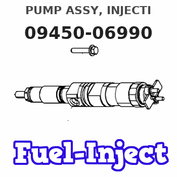
| 001. | PUMP ASSY, INJECTI | 09450-06990 |
Scheme ###:
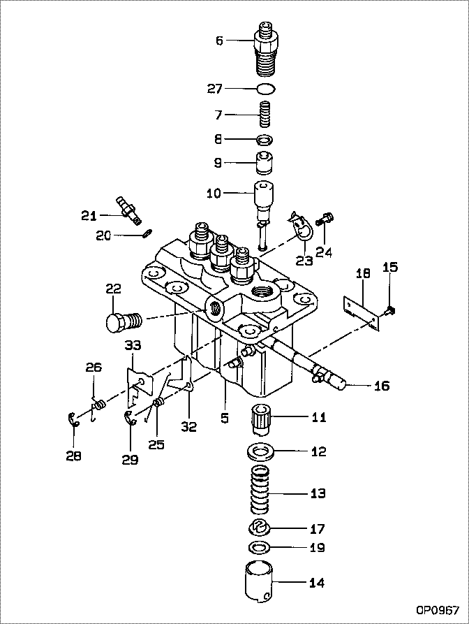
| 000. | [01] | 09450-06990 | PUMP ASSY, INJECTI | 30A6514700 |
| 005. | [01] | 09011-02420 | HOUSING SUB-ASSY, | MM501253 |
| 006. | [04] | 09013-10720 | HOLDER, DELIVERY V | |
| 007. | [04] | 09013-60480 | SPRING, DELIVERY V | |
| 008. | [04] | 09013-70130 | GASKET, DELIVERY V | |
| 009. | [04] | 09014-02250 | VALVE SUB-ASSY, IN | |
| 010. | [04] | 09015-04650 | ELEMENT SUB-ASSY, | |
| 011. | [04] | 09016-10210 | SLEEVE, PLUNGER CO | |
| 012. | [04] | 09016-30082 | SEAT, SPRING, UPR | MM501098 |
| 013. | [04] | 09016-40170 | SPRING, PUMP PLUNG | |
| 014. | [04] | 09017-00170 | TAPPET SUB-ASSY,IN | EZ01775027 |
| 014-001. | [04] | 09017-10022 | TAPPET, INJECTION | |
| 014-002. | [04] | 09217-60010 | ROLLER, FEED PUMP | 09217-60010 |
| 014-003. | [04] | 09017-60020 | PIN, INJECTION PUM | |
| 015. | [04] | 09018-30050 | PIN, INJECTION PUM | |
| 016. | [01] | 09021-00440 | RACK ASSY, CONTROL | |
| 017. | [04] | 09030-10060 | SEAT, SPRING, LWR | EZ0177514 |
| 018. | [02] | 09046-70030 | PLATE | |
| 019. | [4C] | 09031-10310 | PLATE, TAPPET ADJU | |
| 019. | [4C] | 09031-10300 | PLATE, TAPPET ADJU | |
| 019. | [4C] | 09031-10280 | PLATE, TAPPET ADJU | |
| 019. | [4C] | 09031-10170 | PLATE, TAPPET ADJU | FR51530028 |
| 019. | [4C] | 09031-10160 | PLATE, TAPPET ADJU | FR51530027 |
| 019. | [4C] | 09031-10140 | PLATE, TAPPET ADJU | 09031-10140 |
| 019. | [4C] | 09031-10130 | PLATE, TAPPET ADJU | 09031-10130 |
| 019. | [4C] | 09031-10120 | PLATE, TAPPET ADJU | 09031-10120 |
| 019. | [4C] | 09031-10110 | PLATE, TAPPET ADJU | 09031-10110 |
| 019. | [4C] | 09031-10010 | PLATE, TAPPET ADJU | 09031-10010 |
| 020. | [01] | 94901-81020 | WASHER, COPPER PLA | 94901-81020 |
| 021. | [01] | 09314-10260 | NIPPLE, OIL LEAKAG | |
| 022. | [01] | 94918-00310 | SCREW, HOLLOW | 85265-00078 |
| 023. | [03] | 09006-80020 | PLATE, ADJUSTING | |
| 024. | [03] | 94904-80800 | BOLT, WASHER HEAD | MM514195 |
| 025. | [01] | 09055-40470 | SPRING, DIAPHRAGM | |
| 026. | [01] | 09055-40280 | SPRING, DIAPHRAGM | |
| 027. | [04] | 09013-90410 | O-RING | 47X0122700 |
| 027. | [04] | 90802-20150 | O-RING | |
| 028. | [01] | 09089-40020 | E-RING | MM501496 |
| 029. | [01] | 09089-40010 | E-RING | 09089-40010 |
| 032. | [1C] | 09021-95370 | STOPPER | |
| 032. | [1C] | 09021-95360 | STOPPER | MM501747 |
| 032. | [1C] | 09021-93120 | STOPPER | |
| 032. | [1C] | 09021-93110 | STOPPER | |
| 032. | [1C] | 09021-93100 | STOPPER | |
| 032. | [1C] | 09021-93090 | STOPPER | |
| 032. | [1C] | 09021-93080 | STOPPER | |
| 033. | [1C] | 09021-96990 | STOPPER | |
| 033. | [1C] | 09021-97000 | STOPPER | |
| 033. | [1C] | 09021-97010 | STOPPER | |
| 033. | [1C] | 09021-97020 | STOPPER | |
| 033. | [1C] | 09021-97030 | STOPPER | |
| 033. | [1C] | 09021-97040 | STOPPER | |
| 033. | [1C] | 09021-96980 | STOPPER | |
| 033. | [1C] | 09021-96970 | STOPPER | |
| 033. | [1C] | 09021-94130 | STOPPER | |
| 033. | [1C] | 09021-94120 | STOPPER | |
| 033. | [1C] | 09021-94110 | STOPPER | |
| 033. | [1C] | 09021-94100 | STOPPER | |
| 033. | [1C] | 09021-94090 | STOPPER | |
| 033. | [1C] | 09021-94080 | STOPPER | |
| 033. | [1C] | 09021-97050 | STOPPER |
Include in #3:
09450-06990
as PUMP ASSY, INJECTI
Cross reference number
| Part num | Firm num | Firm | Name |
| 09450-06990 | 30A6514700 | PUMP ASSY, INJECTI | |
| 30A6514700 | MITSUBISHI | PUMP ASSY, INJECTI |
Information:
6. Remove fumes disposal tube (1).7. Remove the bolts (4) that hold the timing gear cover to the cylinder block.8. Remove water bonnet (2).9. Remove timing gear cover (3).
Do not cause damage to the crankshaft front seal when the cover is removed.
10. Check the condition of the O-ring seal on the fuel injection pump housing.Install Timing Gear Cover
1. Put clean engine oil on the O-ring seal for the fuel injection pump housing, the crankshaft front seal and wear sleeve.2. Install tool (B) in the crankshaft front seal.3. Install a new gasket on the timing gear cover. Put timing gear cover (1) in position on the dowels in the cylinder block. Make sure it is against the cylinder block all around.4. Install the bolts that hold the cover in position. Remove tool (B) from the crankshaft front seal.5. Install the water bonnet, the fumes disposal tube and the block for the belt tightener bracket.6. Fasten a hoist to the engine and lift it off tool (A). Remove the bar stock from between the cylinder block and oil pan. Tighten the bolts that hold the oil pan to the cylinder block.7. Install the bolts that hold the oil pan to the timing gear cover. Put the engine back on tool (A).8. Install the tube assembly between the oil pan and oil cooler.end by:a) install water temperature regulator (left cylinder head)b) install belt tightener idler pulleyc) install water pumpd) install vibration damper and pulleye) install automatic timing advance