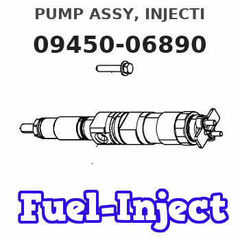
Information pump assy, injecti
Nozzle:
0935003840
Rating:
Components :
| 001. | PUMP ASSY, INJECTI | 09450-06890 |
Scheme ###:
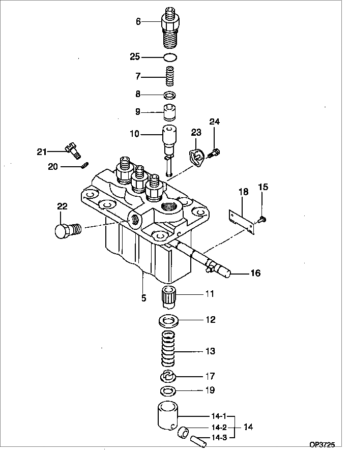
| 000. | [01] | 09450-06890 | PUMP ASSY, INJECTI | 31A6502010 |
| 005. | [01] | 09011-05070 | HOUSING SUB-ASSY, | 47X0104200 |
| 006. | [04] | 09013-10520 | HOLDER, DELIVERY V | |
| 007. | [04] | 09013-60640 | SPRING, DELIVERY V | |
| 008. | [04] | 09013-70130 | GASKET, DELIVERY V | |
| 009. | [04] | 09014-02500 | VALVE SUB-ASSY, IN | 47X0104300 |
| 010. | [04] | 09015-05450 | ELEMENT SUB-ASSY, | 47X0104400 |
| 011. | [04] | 09016-10210 | SLEEVE, PLUNGER CO | |
| 012. | [04] | 09016-30082 | SEAT, SPRING, UPR | MM501098 |
| 013. | [04] | 09016-40170 | SPRING, PUMP PLUNG | |
| 014. | [04] | 09017-00170 | TAPPET SUB-ASSY,IN | EZ01775027 |
| 014-001. | [04] | 09017-10022 | TAPPET, INJECTION | |
| 014-002. | [04] | 09217-60010 | ROLLER, FEED PUMP | 09217-60010 |
| 014-003. | [04] | 09017-60020 | PIN, INJECTION PUM | |
| 015. | [04] | 09018-30050 | PIN, INJECTION PUM | |
| 016. | [01] | 09021-00440 | RACK ASSY, CONTROL | |
| 017. | [04] | 09030-10060 | SEAT, SPRING, LWR | EZ0177514 |
| 018. | [02] | 09046-70030 | PLATE | |
| 019. | [4C] | 09031-10310 | PLATE, TAPPET ADJU | |
| 019. | [4C] | 09031-10300 | PLATE, TAPPET ADJU | |
| 019. | [4C] | 09031-10280 | PLATE, TAPPET ADJU | |
| 019. | [4C] | 09031-10170 | PLATE, TAPPET ADJU | FR51530028 |
| 019. | [4C] | 09031-10160 | PLATE, TAPPET ADJU | FR51530027 |
| 019. | [4C] | 09031-10140 | PLATE, TAPPET ADJU | 09031-10140 |
| 019. | [4C] | 09031-10130 | PLATE, TAPPET ADJU | 09031-10130 |
| 019. | [4C] | 09031-10120 | PLATE, TAPPET ADJU | 09031-10120 |
| 019. | [4C] | 09031-10110 | PLATE, TAPPET ADJU | 09031-10110 |
| 019. | [4C] | 09031-10010 | PLATE, TAPPET ADJU | 09031-10010 |
| 020. | [01] | 94901-81020 | WASHER, COPPER PLA | 94901-81020 |
| 020. | [01] | 09022-20080 | WASHER, FUEL PIPE | MM500114 |
| 021. | [01] | 09024-40180 | SCREW, AIR BLEEDER | |
| 022. | [01] | 94918-00310 | SCREW, HOLLOW | 85265-00078 |
| 023. | [03] | 09006-80020 | PLATE, ADJUSTING | |
| 024. | [03] | 94904-80800 | BOLT, WASHER HEAD | MM514195 |
| 025. | [04] | 90802-20150 | O-RING | |
| 025. | [04] | 09013-90410 | O-RING | 47X0122700 |
Include in #3:
09450-06890
as PUMP ASSY, INJECTI
Cross reference number
| Part num | Firm num | Firm | Name |
| 09450-06890 | 31A6502010 | PUMP ASSY, INJECTI | |
| 31A6502010 | MITSUBISHI | PUMP ASSY, INJECTI |
Information:
2. Remove two short bolts (1) and two longer bolts (2) from manifold (3) and BrakeSaver housing.3. Remove the manifold from the control valve. 4. Remove the three bolts from elbows (5) and the control valve.5. Remove four bolts (4) that hold the control valve to the oil pan.6. Remove the control valve from under the oil pan.7. Make an inspection of the O-ring seals on the manifold and on the control valve. If there is wear or damage make a replacement of the O-ring seals.Install Brakesaver Control Valve
1. Put clean SAE 30 engine oil on O-ring seals (1).2. Put the control valve in position under the oil pan. Install the four bolts that hold the control valve to the oil pan.3. Install the elbow and the bolts that hold it to the side of the control valve. 4. Put SAE 30 engine oil on the O-ring seals of the manifold. Install manifold (2) in the control valve. Install the four bolts that hold the manifold to the BrakeSaver housing.5. Fill the engine with oil. See 3408 TRUCK ENGINE LUBRICATION AND MAINTENANCE GUIDE.Disassemble Brakesaver Control Valve
start by:a) remove BrakeSaver control valve 1. Remove O-ring seals (1) from the valve body.2. Remove four bolts (2) slowly and evenly from cover (4). Remove the cover.
Spring force is behind the cover at removal.
3. Remove cover (3) and the seal from the opposite end of the valve body. 4. Remove spool (8) as an assembly.5. Remove spring (7), stop (10), spring (6) and slug (9).6. Remove the seals and sleeve (5). 7. Remove bolt (11), plate (13) and diaphragm (12) from the spool. Make an inspection of the pin on the spool, and make a replacement of the pin if there is damage or wear.Assemble Brakesaver Control Valve
1. Install diaphragm (4) and plate (8) on valve spool (3). Make alignment of the hole in the plate valve with the pin on the spool. Install the bolt that holds the plate and the diaphragm in position.
When diaphragm (4) is installed on valve spool (3), make sure the fabric side is pulled down over the valve spool to make contact with it and the smooth (rubber coated) side is next to valve body.
2. Install sleeves (1) and the seals in the valve body. 3. Install the valve spool as an assembly into the valve body. As the valve spool is installed, make sure the edge of the diaphragm makes contact all the way around with the groove in the valve body. At this time the valve spool end must extend about 1.50 in. (38.1 mm) from the valve body. Push the valve spool about .25 in. (6.4 mm) - .50 in. (12.7 mm) farther into the valve body until a curved depression is caused between the valve spool and valve body. Make sure there are no wrinkles in the diaphragm. 4. Put cover (9) in position. Install the four bolts that hold the cover on the valve body. Move the valve spool in the