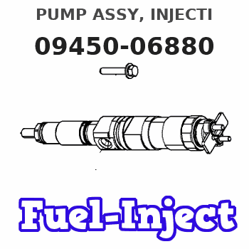
Information pump assy, injecti
Nozzle:
0935003840
Rating:
Components :
| 001. | PUMP ASSY, INJECTI | 09450-06880 |
Scheme ###:
| 000. | [01] | 09450-06880 | PUMP ASSY, INJECTI | 31A6501090 |
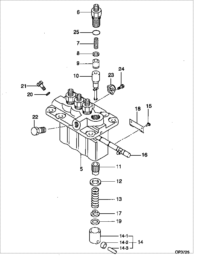
| 005. | [01] | 09011-05070 | HOUSING SUB-ASSY, | 47X0104200 |
| 006. | [04] | 09013-10520 | HOLDER, DELIVERY V | |
| 007. | [04] | 09013-60640 | SPRING, DELIVERY V | |
| 008. | [04] | 09013-70130 | GASKET, DELIVERY V | |
| 009. | [04] | 09014-02500 | VALVE SUB-ASSY, IN | 47X0104300 |
| 010. | [04] | 09015-05450 | ELEMENT SUB-ASSY, | 47X0104400 |
| 011. | [04] | 09016-10210 | SLEEVE, PLUNGER CO | |
| 012. | [04] | 09016-30082 | SEAT, SPRING, UPR | MM501098 |
| 013. | [04] | 09016-40170 | SPRING, PUMP PLUNG | |
| 014. | [04] | 09017-00170 | TAPPET SUB-ASSY,IN | EZ01775027 |
| 014-001. | [04] | 09017-10022 | TAPPET, INJECTION | |
| 014-002. | [04] | 09217-60010 | ROLLER, FEED PUMP | 09217-60010 |
| 014-003. | [04] | 09017-60020 | PIN, INJECTION PUM | |
| 015. | [04] | 09018-30050 | PIN, INJECTION PUM | |
| 016. | [01] | 09021-00440 | RACK ASSY, CONTROL | |
| 017. | [04] | 09030-10060 | SEAT, SPRING, LWR | EZ0177514 |
| 018. | [02] | 09046-70030 | PLATE | |
| 019. | [4C] | 09031-10310 | PLATE, TAPPET ADJU | |
| 019. | [4C] | 09031-10300 | PLATE, TAPPET ADJU | |
| 019. | [4C] | 09031-10280 | PLATE, TAPPET ADJU | |
| 019. | [4C] | 09031-10170 | PLATE, TAPPET ADJU | FR51530028 |
| 019. | [4C] | 09031-10160 | PLATE, TAPPET ADJU | FR51530027 |
| 019. | [4C] | 09031-10140 | PLATE, TAPPET ADJU | 09031-10140 |
| 019. | [4C] | 09031-10130 | PLATE, TAPPET ADJU | 09031-10130 |
| 019. | [4C] | 09031-10120 | PLATE, TAPPET ADJU | 09031-10120 |
| 019. | [4C] | 09031-10110 | PLATE, TAPPET ADJU | 09031-10110 |
| 019. | [4C] | 09031-10010 | PLATE, TAPPET ADJU | 09031-10010 |
| 020. | [01] | 94901-81020 | WASHER, COPPER PLA | 94901-81020 |
| 020. | [01] | 09022-20080 | WASHER, FUEL PIPE | MM500114 |
| 021. | [01] | 09024-40180 | SCREW, AIR BLEEDER | |
| 022. | [01] | 94918-00310 | SCREW, HOLLOW | 85265-00078 |
| 023. | [03] | 09006-80020 | PLATE, ADJUSTING | |
| 024. | [03] | 94904-80800 | BOLT, WASHER HEAD | MM514195 |
| 025. | [04] | 90802-20150 | O-RING | |
| 025. | [04] | 09013-90410 | O-RING | 47X0122700 |
Include in #3:
09450-06880
as PUMP ASSY, INJECTI
Cross reference number
| Part num | Firm num | Firm | Name |
| 09450-06880 | 31A6501090 | PUMP ASSY, INJECTI | |
| 31A6501090 | MITSUBISHI | PUMP ASSY, INJECTI |
Information:
2. Remove oil filter base support (2), air line (3) and oil level gauge tube (4). Remove the right lifting eye (1) and the left lifting eye. 3. Remove glow plug leads (5) and the 3/8 in. bolts from the cylinder head. Glow plug leads are on the precombustion engine only.4. Install two 5/16"-18 NC forged eyebolts and nuts in the cylinder head. Fasten a hoist to the cylinder head.5. Remove cylinder head bolts (6) and the washers. Clean all debris or foreign material from the "V" of the engine before removal of the cylinder head.6. Remove the cylinder head. Weight of the cylinder head is 200 lb. (90 kg). Put a cover over the intake manifold portion of the cylinder head to keep dirt and foreign material out.
Do not put the cylinder head down on a flat surface. This can cause damage to the fuel injection valves.
A new spacer plate gasket must be installed when the cylinder head is removed. See REMOVE AND INSTALL SPACER PLATE.Install Cylinder Head
1. Clean the spacer plate and the bottom surface of the cylinder head. Put a new cylinder head gasket (3) and seals (4) in position on the spacer plate as shown.2. Fasten a hoist to cylinder head (2) and put it in position over dowels (5) in the cylinder block.3. Put clean SAE 30 oil on the threads of the bolts that hold the cylinder head in position. Install the bolts and washers and tighten them to the correct torque as follows: a) Tighten bolts 1 through 14 in number sequence to a torque of 200 20 lb.ft. (270 25 N m).b) Tighten bolts 1 through 14 in number sequence to a torque of 330 15 lb.ft. (447 20 N m).c) Tighten bolts 1 through 14 again in number sequence to a torque of 330 15 lb.ft. (447 20 N m).d) Install the rocker shaft assembly and push rods.e) Tighten bolts 15 through 18 in number sequence to a torque of 200 20 lb.ft. (270 25 N m).f) Tighten bolts 15 through 18 in number sequence to a torque of 330 15 lb.ft. (447 20 N m).g) Tighten bolts 15 through 18 again in number sequence to a torque of 330 15 lb.ft. (447 20 N m).4. Install the glow plug leads and the 3/8 in. bolts in the cylinder head. Tighten the bolts to a torque of 32 5 lb.ft. (43 7 N m). If studs (1) were removed, install new studs and tighten them to a torque of 20 3 lb.ft. (25 4 N m).5. Make an adjustment for the valve clearance. The clearance must be .015 .003 in. (0.38 0.07 mm) for intake and .030 .003 in. (0.76 0.07 mm) for exhaust. See VALVE CLEARANCE SETTING in TESTING AND ADJUSTING.6. Install the left and right lifting eyes.7. Install the oil level gauge tube, air line and oil