Information pump assy, injecti
Nozzle:
0935003840
Rating:
Components :
| 001. | PUMP ASSY, INJECTI | 09450-06860 |
Scheme ###:
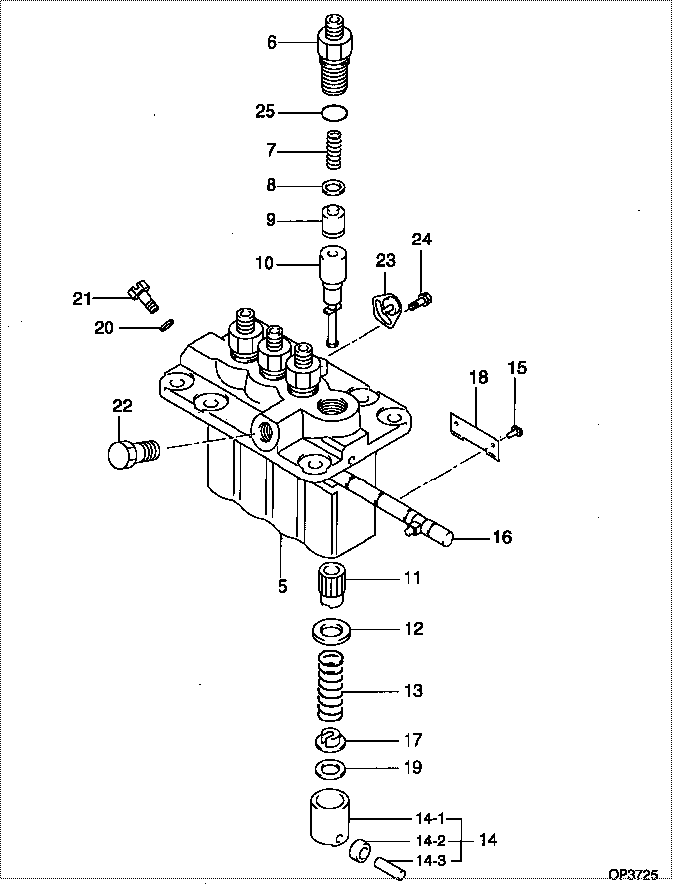
| 000. | [01] | 09450-06860 | PUMP ASSY, INJECTI | 31A6501080 |
| 005. | [01] | 09011-05070 | HOUSING SUB-ASSY, | 47X0104200 |
| 006. | [04] | 09013-10520 | HOLDER, DELIVERY V | |
| 007. | [04] | 09013-60540 | SPRING, DELIVERY V | |
| 008. | [04] | 09013-70130 | GASKET, DELIVERY V | |
| 009. | [04] | 09014-02610 | VALVE SUB-ASSY, IN | 47X0107700 |
| 010. | [04] | 09015-05550 | ELEMENT SUB-ASSY, | 47X0105400 |
| 011. | [04] | 09016-10210 | SLEEVE, PLUNGER CO | |
| 012. | [04] | 09016-30082 | SEAT, SPRING, UPR | MM501098 |
| 013. | [04] | 09016-40170 | SPRING, PUMP PLUNG | |
| 014. | [04] | 09017-00170 | TAPPET SUB-ASSY,IN | EZ01775027 |
| 014-001. | [04] | 09017-10022 | TAPPET, INJECTION | |
| 014-002. | [04] | 09217-60010 | ROLLER, FEED PUMP | 09217-60010 |
| 014-003. | [04] | 09017-60020 | PIN, INJECTION PUM | |
| 015. | [04] | 09018-30050 | PIN, INJECTION PUM | |
| 016. | [01] | 09021-00440 | RACK ASSY, CONTROL | |
| 017. | [04] | 09030-10060 | SEAT, SPRING, LWR | EZ0177514 |
| 018. | [02] | 09046-70030 | PLATE | |
| 019. | [4C] | 09031-10310 | PLATE, TAPPET ADJU | |
| 019. | [4C] | 09031-10300 | PLATE, TAPPET ADJU | |
| 019. | [4C] | 09031-10280 | PLATE, TAPPET ADJU | |
| 019. | [4C] | 09031-10170 | PLATE, TAPPET ADJU | FR51530028 |
| 019. | [4C] | 09031-10160 | PLATE, TAPPET ADJU | FR51530027 |
| 019. | [4C] | 09031-10140 | PLATE, TAPPET ADJU | 09031-10140 |
| 019. | [4C] | 09031-10130 | PLATE, TAPPET ADJU | 09031-10130 |
| 019. | [4C] | 09031-10120 | PLATE, TAPPET ADJU | 09031-10120 |
| 019. | [4C] | 09031-10110 | PLATE, TAPPET ADJU | 09031-10110 |
| 019. | [4C] | 09031-10010 | PLATE, TAPPET ADJU | 09031-10010 |
| 020. | [01] | 94901-81020 | WASHER, COPPER PLA | 94901-81020 |
| 020. | [01] | 09022-20080 | WASHER, FUEL PIPE | MM500114 |
| 021. | [01] | 09024-40180 | SCREW, AIR BLEEDER | |
| 022. | [01] | 94918-00310 | SCREW, HOLLOW | 85265-00078 |
| 023. | [03] | 09006-80020 | PLATE, ADJUSTING | |
| 024. | [03] | 94904-80800 | BOLT, WASHER HEAD | MM514195 |
| 025. | [04] | 90802-20150 | O-RING | |
| 025. | [04] | 09013-90410 | O-RING | 47X0122700 |
Include in #3:
09450-06860
as PUMP ASSY, INJECTI
Cross reference number
| Part num | Firm num | Firm | Name |
| 09450-06860 | 31A6501080 | PUMP ASSY, INJECTI | |
| 31A6501080 | MITSUBISHI | PUMP ASSY, INJECTI |
Information:
start by: a) remove valve cover The following steps can be used for the direct injection and precombustion engines except the direct injection engines do not have glow plugs and wires. 1. Remove clip (2) for glow plug wire and fuel injection line (1). Use tool (A) to remove the fuel injection line from the fuel injection valve. 2. Remove fuel line adapters (4) and the spacers from valve cover base (3). Remove the O-ring seal from the adapter.3. Remove bolts (5) and washers (6) that hold rocker shaft assembly (7).4. Remove the rocker shaft assembly. All push rods except those at each end can be removed without removal of the rocker shaft.5. Remove the push rods from the cylinder head.6. Remove intake bridge (9) and exhaust bridge (8) from the bridge dowels. Put identification on the parts to prevent a mix at installation.Install Rocker Shaft Assembly And Push Rods
1. Put clean SAE 30 oil on the bridge dowel and install exhaust bridge (3) and intake bridge (2) in their correct locations.2. Put finger pressure on top of the bridge and turn the adjusting screw clockwise until it makes contact with the valve stem. Turn the adjusting screw 20° to 30° more. Hold the adjusting screw in this position and tighten the locknut to a torque of 22 3 lb.ft. (28 4 N m).3. Put clean SAE 30 oil on top of the pad on the bridge.4. Install push rods (1) and the rocker shaft assembly. Put clean SAE 30 oil on the threads of the bolts that hold the rocker shaft in position. Install the bolts and washers. 5. Tighten the bolts that hold rocker shaft assembly (8) as follows: a) Tighten the bolts in number sequence to a torque of 200 20 lb.ft. (270 25 N m).b) Tighten the bolts again in number sequence to a torque of 330 15 lb.ft. (447 20 N m).c) Tighten the bolts again in number sequence to a torque of 330 15 lb.ft. (447 20 N m).6. Make an adjustment of the correct valve clearances. The clearance must be .015 in. (0.38 mm) for intake and .030 in. (0.76 mm) for exhaust. See VALVE CLEARANCE SETTING in TESTING AND ADJUSTING. 7. Put clean SAE 30 oil on the O-ring seal and install O-ring seal (9) on adapter (10). Install the adapter in valve cover base (11). Install the locks, spacers and nuts that hold it.8. Install the fuel injection line on the adapter and the fuel injection valve. Tighten the nut on the fuel injection valve with tool (A) to a torque of 55 5 lb.ft. (75 7 N m). Tighten the nut on the adapter with tool (A) to a torque of 30 5 lb.ft. (40 7 N m).9. Connect the wire to the glow plug. Connect the clip for the glow plug to the fuel injection line with the wire on the same side as the
1. Put clean SAE 30 oil on the bridge dowel and install exhaust bridge (3) and intake bridge (2) in their correct locations.2. Put finger pressure on top of the bridge and turn the adjusting screw clockwise until it makes contact with the valve stem. Turn the adjusting screw 20° to 30° more. Hold the adjusting screw in this position and tighten the locknut to a torque of 22 3 lb.ft. (28 4 N m).3. Put clean SAE 30 oil on top of the pad on the bridge.4. Install push rods (1) and the rocker shaft assembly. Put clean SAE 30 oil on the threads of the bolts that hold the rocker shaft in position. Install the bolts and washers. 5. Tighten the bolts that hold rocker shaft assembly (8) as follows: a) Tighten the bolts in number sequence to a torque of 200 20 lb.ft. (270 25 N m).b) Tighten the bolts again in number sequence to a torque of 330 15 lb.ft. (447 20 N m).c) Tighten the bolts again in number sequence to a torque of 330 15 lb.ft. (447 20 N m).6. Make an adjustment of the correct valve clearances. The clearance must be .015 in. (0.38 mm) for intake and .030 in. (0.76 mm) for exhaust. See VALVE CLEARANCE SETTING in TESTING AND ADJUSTING. 7. Put clean SAE 30 oil on the O-ring seal and install O-ring seal (9) on adapter (10). Install the adapter in valve cover base (11). Install the locks, spacers and nuts that hold it.8. Install the fuel injection line on the adapter and the fuel injection valve. Tighten the nut on the fuel injection valve with tool (A) to a torque of 55 5 lb.ft. (75 7 N m). Tighten the nut on the adapter with tool (A) to a torque of 30 5 lb.ft. (40 7 N m).9. Connect the wire to the glow plug. Connect the clip for the glow plug to the fuel injection line with the wire on the same side as the