Information pump assy, injecti
Nozzle:
0935003840
Rating:
Components :
| 001. | PUMP ASSY, INJECTI | 09450-06850 |
Scheme ###:
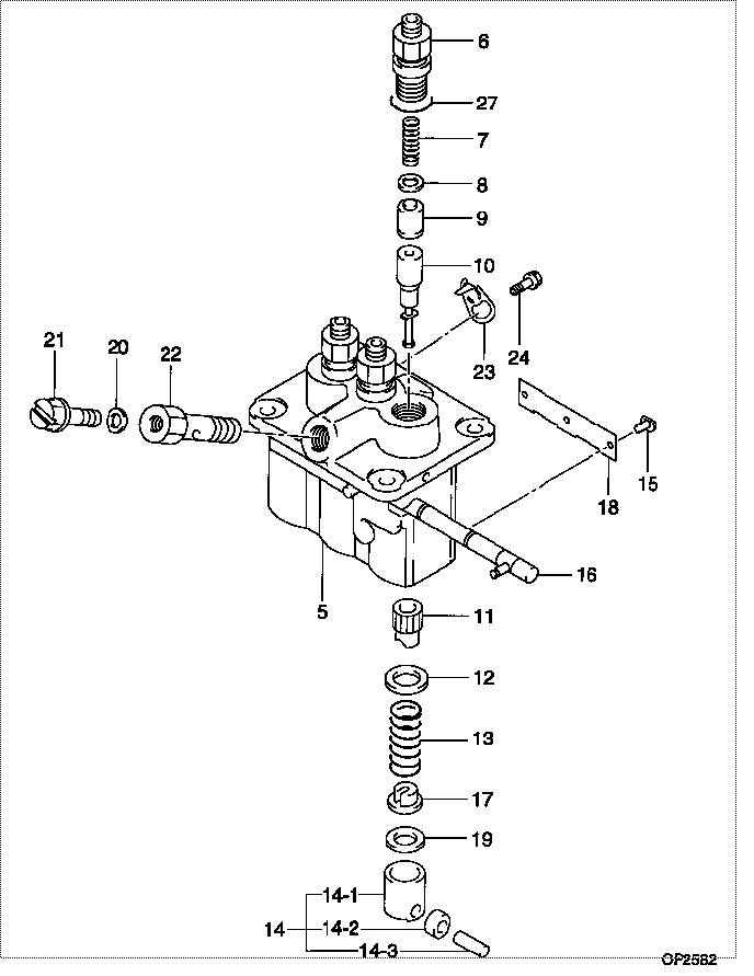
| 000. | [01] | 09450-06850 | PUMP ASSY, INJECTI | 31B6502060 |
| 005. | [01] | 09011-05110 | HOUSING SUB-ASSY, | 47X0106100 |
| 006. | [03] | 09013-10520 | HOLDER, DELIVERY V | |
| 007. | [03] | 09013-60540 | SPRING, DELIVERY V | |
| 008. | [03] | 09013-70130 | GASKET, DELIVERY V | |
| 009. | [03] | 09014-02610 | VALVE SUB-ASSY, IN | 47X0107700 |
| 010. | [03] | 09015-05550 | ELEMENT SUB-ASSY, | 47X0105400 |
| 011. | [03] | 09016-10210 | SLEEVE, PLUNGER CO | |
| 012. | [03] | 09016-30082 | SEAT, SPRING, UPR | MM501098 |
| 013. | [03] | 09016-40170 | SPRING, PUMP PLUNG | |
| 014. | [03] | 09017-00170 | TAPPET SUB-ASSY,IN | EZ01775027 |
| 014-001. | [03] | 09017-10021 | TAPPET, INJECTION | |
| 014-002. | [03] | 09217-60010 | ROLLER, FEED PUMP | 09217-60010 |
| 014-003. | [03] | 09017-60020 | PIN, INJECTION PUM | |
| 015. | [03] | 09018-30050 | PIN, INJECTION PUM | |
| 016. | [01] | 09021-00470 | RACK ASSY, CONTROL | |
| 017. | [03] | 09030-10060 | SEAT, SPRING, LWR | EZ0177514 |
| 018. | [01] | 09046-70040 | PLATE | |
| 019. | [3C] | 09031-10310 | PLATE, TAPPET ADJU | |
| 019. | [3C] | 09031-10300 | PLATE, TAPPET ADJU | |
| 019. | [3C] | 09031-10280 | PLATE, TAPPET ADJU | |
| 019. | [3C] | 09031-10170 | PLATE, TAPPET ADJU | FR51530028 |
| 019. | [3C] | 09031-10160 | PLATE, TAPPET ADJU | FR51530027 |
| 019. | [3C] | 09031-10140 | PLATE, TAPPET ADJU | 09031-10140 |
| 019. | [3C] | 09031-10130 | PLATE, TAPPET ADJU | 09031-10130 |
| 019. | [3C] | 09031-10120 | PLATE, TAPPET ADJU | 09031-10120 |
| 019. | [3C] | 09031-10110 | PLATE, TAPPET ADJU | 09031-10110 |
| 019. | [3C] | 09031-10010 | PLATE, TAPPET ADJU | 09031-10010 |
| 020. | [01] | 94901-81020 | WASHER, COPPER PLA | 94901-81020 |
| 020. | [01] | 09022-20080 | WASHER, FUEL PIPE | MM500114 |
| 021. | [01] | 09024-40180 | SCREW, AIR BLEEDER | |
| 022. | [01] | 09024-50210 | SCREW, HOLLOW | |
| 023. | [02] | 09006-80020 | PLATE, ADJUSTING | |
| 024. | [02] | 94904-80800 | BOLT, WASHER HEAD | MM514195 |
| 027. | [03] | 90802-20150 | O-RING | |
| 027. | [03] | 09013-90410 | O-RING | 47X0122700 |
Include in #3:
09450-06850
as PUMP ASSY, INJECTI
Cross reference number
| Part num | Firm num | Firm | Name |
| 09450-06850 | 31B6502060 | PUMP ASSY, INJECTI | |
| 31B6502060 | MITSUBISHI | PUMP ASSY, INJECTI |
Information:
start by:a) remove valve covers
Do not let the tops of the fuel nozzles turn when the fuel lines are loosened. The nozzles will be damaged if the top of the nozzles turn in the body.
1. Use tooling (A) to loosen fuel injection line nut (1) at the fuel injection nozzles. 2. Disconnect fuel injection line nut (2) from head adapter nut (3).3. Remove adapter nut (3) and the O-ring seal.4. Move adapter (4) out of the valve cover base, and remove fuel injection line (1). 5. If necessary, remove seal (5) from fuel injection line (1). 6. Remove bolt (7) that holds clamp (6). Clamp (6) cannot be removed until fuel injection nozzle (8) is lifted 25.0 mm (1.00 in.).7. Remove fuel injection nozzle (8) with tooling (B) as follows: a. Install 6V6983 Adapter and 6V4152 Screw (9) [part of tooling (B)] into fuel injection nozzle (8). b. Install 6V6982 Tube Assembly (11) over the 6V4152 Screw. Use 2S5658 Washer and 1B2406 Nut (10) on the 6V4152 Screw to pull fuel injection nozzle (8) from the adapter. Items (10) and (11) are part of tooling (B).
A replacement of compression seal washer (13) and of carbon dam seal (12) must be made each time the fuel injection nozzle is removed. Be sure that the replacement compression seal washer (13) is the same color code and part number as the original compression seal washer. If the wrong thickness washer is used, engine damage could occur. See the Specifications section of this book for more information.
8. Remove carbon dam seal (12) and compression seal washer (13) from fuel injection nozzle (8).Install Fuel Injection Nozzles
1. Use tool (D) to clean adapter bore (1) for the fuel injection nozzle. Use a tap driver to turn tool (D). 2. Install compression seal washer (3) on fuel injection nozzle (4).3. Use tool (A) to install carbon dam seal (2) on fuel injection nozzle (4). Refer to Special Instruction SEHS7292 for the use of tooling (C). 4. Install fuel injection nozzle (4) and clamp (5) as a unit. Install the bolt through the clamp into the adapter. 5. Install O-ring seal (6) on fuel injection line (7) and put clean diesel fuel on it. 6. Install fuel injection line (7). Move adapter (8) into position in the rocker arm cover base.
Do not let the tops of the fuel nozzles turn when the fuel lines are tightened. The nozzles will be damaged if the top of the nozzles turn in the body.
7. Use tooling (B) to tighten the inner fuel line nuts to a torque of 41 7 N m (30 5 lb.ft.). 8. Put clean diesel fuel oil on O-ring seal (11). Install O-ring seal (11) and nut (10). Tighten nut (10) to a torque of 30 5 N m (22 4 lb.ft.).9. Install nut (9) for the fuel injection line, and tighten the fuel injection line nut to a torque of 41 7 N m (30 5 lb.ft.).end by:a)