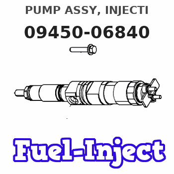
Information pump assy, injecti
Nozzle:
0935003840
Rating:
You can express buy:
USD 867.38
08-06-2025
08-06-2025
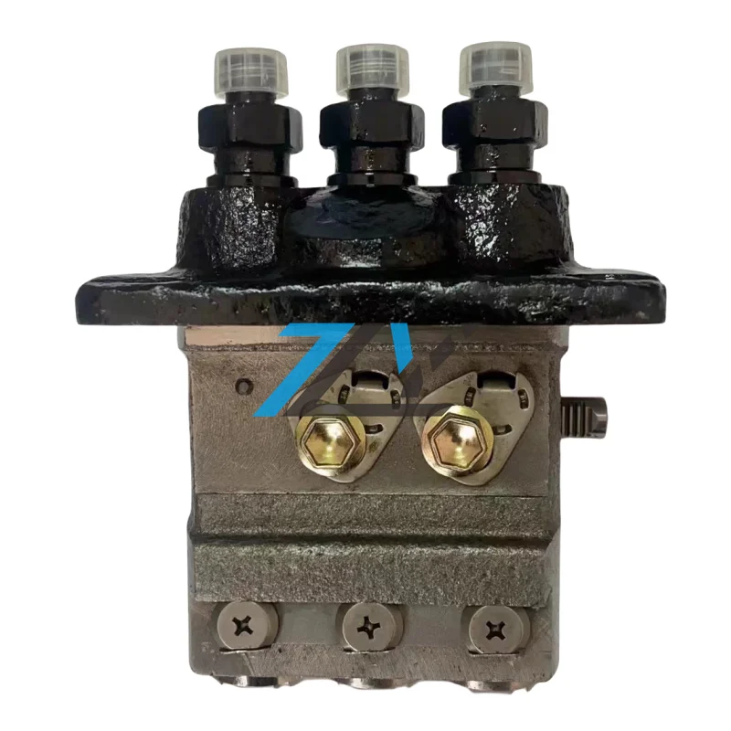
094500-6840 Diesel pump Fuel Injection Pump 0945006840 Excavator spare parts
Components :
| 001. | PUMP ASSY, INJECTI | 09450-06840 |
Scheme ###:
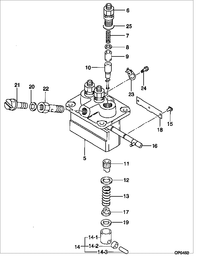
| 000. | [01] | 09450-06840 | PUMP ASSY, INJECTI | 31B6502050 |
| 005. | [01] | 09011-05110 | HOUSING SUB-ASSY, | 47X0106100 |
| 006. | [03] | 09013-10520 | HOLDER, DELIVERY V | |
| 007. | [03] | 09013-60540 | SPRING, DELIVERY V | |
| 008. | [03] | 09013-70130 | GASKET, DELIVERY V | |
| 009. | [03] | 09014-02600 | VALVE SUB-ASSY, IN | 47X0107400 |
| 010. | [03] | 09015-05550 | ELEMENT SUB-ASSY, | 47X0105400 |
| 011. | [03] | 09016-10210 | SLEEVE, PLUNGER CO | |
| 012. | [03] | 09016-30082 | SEAT, SPRING, UPR | MM501098 |
| 013. | [03] | 09016-40170 | SPRING, PUMP PLUNG | |
| 014. | [03] | 09017-00170 | TAPPET SUB-ASSY,IN | EZ01775027 |
| 014-001. | [03] | 09017-10021 | TAPPET, INJECTION | |
| 014-002. | [03] | 09217-60010 | ROLLER, FEED PUMP | 09217-60010 |
| 014-003. | [03] | 09017-60020 | PIN, INJECTION PUM | |
| 015. | [03] | 09018-30050 | PIN, INJECTION PUM | |
| 016. | [01] | 09021-00470 | RACK ASSY, CONTROL | |
| 017. | [03] | 09030-10060 | SEAT, SPRING, LWR | EZ0177514 |
| 018. | [01] | 09046-70040 | PLATE | |
| 019. | [3C] | 09031-10010 | PLATE, TAPPET ADJU | 09031-10010 |
| 019. | [3C] | 09031-10310 | PLATE, TAPPET ADJU | |
| 019. | [3C] | 09031-10300 | PLATE, TAPPET ADJU | |
| 019. | [3C] | 09031-10280 | PLATE, TAPPET ADJU | |
| 019. | [3C] | 09031-10170 | PLATE, TAPPET ADJU | FR51530028 |
| 019. | [3C] | 09031-10160 | PLATE, TAPPET ADJU | FR51530027 |
| 019. | [3C] | 09031-10140 | PLATE, TAPPET ADJU | 09031-10140 |
| 019. | [3C] | 09031-10130 | PLATE, TAPPET ADJU | 09031-10130 |
| 019. | [3C] | 09031-10120 | PLATE, TAPPET ADJU | 09031-10120 |
| 019. | [3C] | 09031-10110 | PLATE, TAPPET ADJU | 09031-10110 |
| 020. | [01] | 94901-81020 | WASHER, COPPER PLA | 94901-81020 |
| 020. | [01] | 09022-20080 | WASHER, FUEL PIPE | MM500114 |
| 021. | [01] | 09024-40180 | SCREW, AIR BLEEDER | MM501152 |
| 022. | [01] | 09024-50210 | SCREW, HOLLOW | |
| 023. | [02] | 09006-80020 | PLATE, ADJUSTING | |
| 024. | [02] | 94904-80800 | BOLT, WASHER HEAD | MM514195 |
| 025. | [03] | 90802-20150 | O-RING |
Include in #3:
09450-06840
as PUMP ASSY, INJECTI
Cross reference number
| Part num | Firm num | Firm | Name |
| 09450-06840 | 31B6502050 | PUMP ASSY, INJECTI | |
| 31B6502050 | MITSUBISHI | PUMP ASSY, INJECTI |
Information:
start by:a) remove valve cover 1. Use tool (A) to disconnect fuel line assemblies (1) from the fuel injection valves and valve base adapters. Remove fuel line assemblies (1). 2. Remove push rods (2) with tool (B). 3. Remove valve bridges (3) from the bridge dowels. 4. Remove the nuts that hold the fuel injection valve assemblies in place. Use tool (C) to remove fuel injection valves (4) from the direct injection adapters. 5. Use tool (D) to remove direct injection adapters (5) and gaskets from the cylinder heads.Install Direct Injection Adapters
1. Put 5P3931 Anti-Seize Compound on the threads of direct injection adapters (1).2. Put liquid soap on O-ring seal (3) and the adapter bore in the cylinder head. Install O-ring seal (3) on the adapter.3. Install adapter (1) and gasket (2) in the cylinder head. Use tool (A) to tighten the adapter to a torque of 150 10 lb.ft. (205 14 N m). 4. Put a small amount of clean engine oil on the bridge dowels. Install valve bridges (4). 5. Put a small amount of diesel fuel in the direct injection adapter bore. Install fuel injection valves (5) with tool (B). Tighten the nuts that hold the injection valves in place to a torque of 55 5 lb.ft. (75 7 N m). 6. Install push rods (9) with tool (C).7. Put a small amount of diesel fuel on O-ring seal (6) and install fuel line assemblies (8). Tighten fuel line nuts (7) to a torque of 30 5 lb.ft. (40 7 N m) with tool (D).end by:a) install valve covers
1. Put 5P3931 Anti-Seize Compound on the threads of direct injection adapters (1).2. Put liquid soap on O-ring seal (3) and the adapter bore in the cylinder head. Install O-ring seal (3) on the adapter.3. Install adapter (1) and gasket (2) in the cylinder head. Use tool (A) to tighten the adapter to a torque of 150 10 lb.ft. (205 14 N m). 4. Put a small amount of clean engine oil on the bridge dowels. Install valve bridges (4). 5. Put a small amount of diesel fuel in the direct injection adapter bore. Install fuel injection valves (5) with tool (B). Tighten the nuts that hold the injection valves in place to a torque of 55 5 lb.ft. (75 7 N m). 6. Install push rods (9) with tool (C).7. Put a small amount of diesel fuel on O-ring seal (6) and install fuel line assemblies (8). Tighten fuel line nuts (7) to a torque of 30 5 lb.ft. (40 7 N m) with tool (D).end by:a) install valve covers