Information pump assy, injecti
Nozzle:
0935003840
Rating:
Components :
| 001. | PUMP ASSY, INJECTI | 09450-06820 |
Scheme ###:
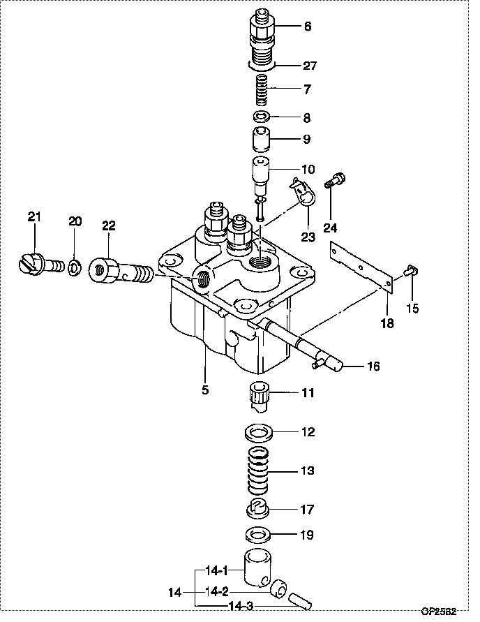
| 000. | [01] | 09450-06820 | PUMP ASSY, INJECTI | 31B6502030 |
| 005. | [01] | 09011-05110 | HOUSING SUB-ASSY, | 47X0106100 |
| 006. | [03] | 09013-10520 | HOLDER, DELIVERY V | |
| 007. | [03] | 09013-60540 | SPRING, DELIVERY V | |
| 008. | [03] | 09013-70130 | GASKET, DELIVERY V | |
| 009. | [03] | 09014-02610 | VALVE SUB-ASSY, IN | 47X0107700 |
| 010. | [03] | 09015-05550 | ELEMENT SUB-ASSY, | 47X0105400 |
| 011. | [03] | 09016-10210 | SLEEVE, PLUNGER CO | |
| 012. | [03] | 09016-30082 | SEAT, SPRING, UPR | MM501098 |
| 013. | [03] | 09016-40170 | SPRING, PUMP PLUNG | |
| 014. | [03] | 09017-00170 | TAPPET SUB-ASSY,IN | EZ01775027 |
| 014-001. | [03] | 09017-10021 | TAPPET, INJECTION | |
| 014-002. | [03] | 09217-60010 | ROLLER, FEED PUMP | 09217-60010 |
| 014-003. | [03] | 09017-60020 | PIN, INJECTION PUM | |
| 015. | [03] | 09018-30050 | PIN, INJECTION PUM | |
| 016. | [01] | 09021-00470 | RACK ASSY, CONTROL | |
| 017. | [03] | 09030-10060 | SEAT, SPRING, LWR | EZ0177514 |
| 018. | [01] | 09046-70040 | PLATE | |
| 019. | [3C] | 09031-10310 | PLATE, TAPPET ADJU | |
| 019. | [3C] | 09031-10300 | PLATE, TAPPET ADJU | |
| 019. | [3C] | 09031-10280 | PLATE, TAPPET ADJU | |
| 019. | [3C] | 09031-10170 | PLATE, TAPPET ADJU | FR51530028 |
| 019. | [3C] | 09031-10160 | PLATE, TAPPET ADJU | FR51530027 |
| 019. | [3C] | 09031-10140 | PLATE, TAPPET ADJU | 09031-10140 |
| 019. | [3C] | 09031-10130 | PLATE, TAPPET ADJU | 09031-10130 |
| 019. | [3C] | 09031-10120 | PLATE, TAPPET ADJU | 09031-10120 |
| 019. | [3C] | 09031-10110 | PLATE, TAPPET ADJU | 09031-10110 |
| 019. | [3C] | 09031-10010 | PLATE, TAPPET ADJU | 09031-10010 |
| 020. | [01] | 94901-81020 | WASHER, COPPER PLA | 94901-81020 |
| 020. | [01] | 09022-20080 | WASHER, FUEL PIPE | MM500114 |
| 021. | [01] | 09024-40180 | SCREW, AIR BLEEDER | |
| 022. | [01] | 09024-50210 | SCREW, HOLLOW | |
| 023. | [02] | 09006-80020 | PLATE, ADJUSTING | |
| 024. | [02] | 94904-80800 | BOLT, WASHER HEAD | MM514195 |
| 027. | [03] | 90802-20150 | O-RING | |
| 027. | [03] | 09013-90410 | O-RING | 47X0122700 |
Include in #3:
09450-06820
as PUMP ASSY, INJECTI
Cross reference number
| Part num | Firm num | Firm | Name |
| 09450-06820 | 31B6502030 | PUMP ASSY, INJECTI | |
| 31B6502030 | MITSUBISHI | PUMP ASSY, INJECTI |
Information:
1. Remove bolt (4). Remove lever (5) and the rod from the governor.2. Remove lockwire (2). Remove bolts (1) and cover (3) from the governor housing. Check the condition of the gasket under the cover. If the gasket has damage, use a new part for replacement. 3. Remove the bolt from stop collar (6). Remove stop collar (6). Remove the collar and spring from below collar (6). 4. Install tool (A) in the fuel injection pump housing. Make sure the correct end of tool (A) is used. Tool (A) is in position when it is against the shoulder of the groove in the rack. The racks are now in the center (zero) position.5. Remove bolts (8) and governor housing (7). 6. Disconnect fuel lines (11) from the governor plate.7. Remove bolts (10) and governor plate (9). Check the condition of the gasket under the plate. If the gasket has damage, use a new part for replacement. It is possible to remove the governor and governor plate as a unit. The above steps must be followed before the governor can be installed again on the injection pump housing.Install Governor (Earlier)
The driver assembly must be removed from the governor plate before the governor plate is installed in the injection pump housing.
1. Install a new gasket on the injection pump housing. 2. Put governor plate (1) in position on the fuel pump housing. Make sure the dowels in governor plate (1) are in alignment with the holes in the injection pump housing. The racks must be held against the rack stop pin and the governor lever engaged in the groove (slot) in the left hand rack. 3. Install stop (3) in gear (4). Make sure the wide space in stop (3) is in alignment with the wide space on the drive pinion assembly.4. Install drive gear assembly (2). 5. Make an alignment of the holes in gear (4), the stop and drive assembly. Install the pin and ring (5) that hold the unit together. 6. Install the gasket and governor housing (8) on the governor plate.7. Install the spring, collar and stop collar (7). Install the bolt in the collar to hold it.8. Check the governor adjustment. See GOVERNOR ADJUSTMENTS in TESTING AND ADJUSTING.9. Install the gasket and cover (6) on the governor housing. Make sure the dowel in the cover is in alignment with the notch in collar (7). Install the bolts that hold the cover in position. Install a new lockwire.10. Connect the fuel lines to the governor plate.11. Install the lever for the governor control.12. Remove tool (A) from the injection pump housing.end by:a) install fuel ratio control